 EK
EKNote: The content from this project log was from Sept. 5th.
We were still waiting for the boxes to arrive to Leo and Tobi (luckily, now, as of writing this, Leo’s box has arrived and Tobi should be receiving it today). Remote debugging testing code proved to be unproductive for numerous reasons. The next step was for me to dive into programming the basic functionality and debugging since I had all the pieces here.
Power Jumper
First change was making the Vcc - Usb power jumper tied on Buoy A and B. This means that everything would be powered on from the usb port. The switching of the jumper was time consuming during the debugging process.
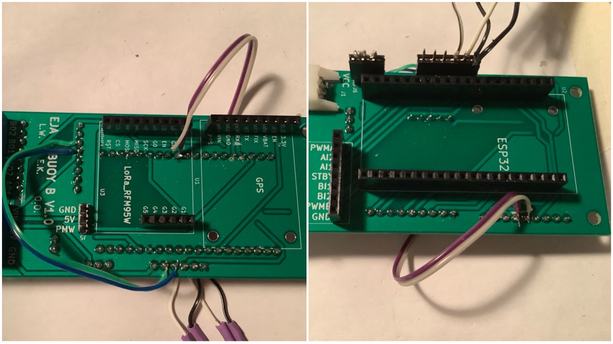
GPS - Buoy B
Next change was moving the GPS from Serial0 to Serial2. The reason for moving is because Serial0 is used as a programming and debug port. This meant that programming did not work when the GPS was powered on. Serial2 is on GPIO 17 (TX) and GPIO 16 (RX). The Ultimate GPS logic level is 3.3V, same as the ESP32. In order to move to those pins, the motor controller channel B pins had to be moved.
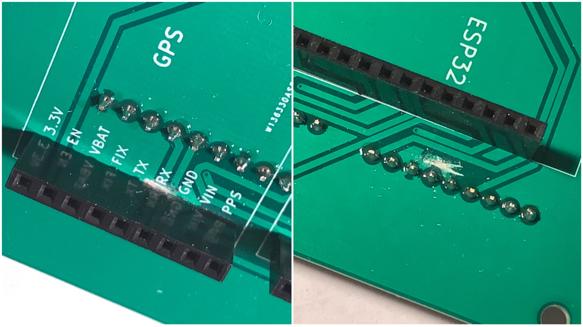
Cutting motor controller traces:

Cutting GPS TX & RX traces:

Conductivity test to make sure the traces were cut:

New wires added:
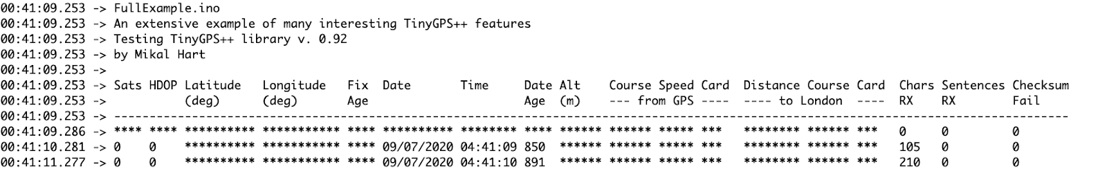
The next step was to use the TinyGPS++ library. This is what we used for Bowie the robot, and it has proven to be extremely useful at parsing the NMEA data. After holding the Buoy B at the window, it resulted in a fix and data:

One thing about the changes - the motor change moves the wires to the pins that Leo proposed the RTC to be added to. An option is to remove motor channel B all together. It’s likely that only one channel would be needed for the foreseeable applications for now.
GPS - Buoy A
Next up is a similar change with Buoy A. Buoy A is different, as it has the SIM7600 on Serial2. At this point I figured using Serial1 for GPS would be fine, however that proved to be false. The reason why is because the pins Serial1 is on (9 & 10, aka SD3 & SD2) are used by flash when QIO is enabled. Next, I tried uploading in DIO, QOUT, and DOUT. DOUT was the only one that worked without Guru errors. However, no data was received. A quick swap of RX and TX was done just in case, however it was the same result.
Time to try a software serial option. Moved the GPS to software serial on pins IO12 and IO0. It works, however cannot upload when those pins are in use, and so have to disconnect the power jumper. To be clear regarding the pins: GPS RX -> IO12, and GPS TX -> IO0. These can be swapped by the SoftwareSerial object anyway.
Cutting the GPS traces:
Adding the GPS wire:

Seeing it work (yay!):

LoRa
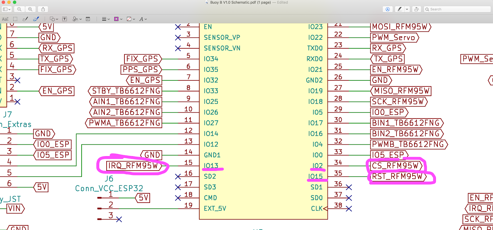
The LoRa connection is working. The reason why it was not working through remote debugging was because the pins were defined incorrectly through multiple tests. Additionally, the test code was trying to test too many subsystems at once. The solution was to 1) read the datasheet, 2) write the proper numbers in the LoRa library example code. After going back to the basics, the LoRa code worked fine between Buoy A & B to the Onboard Gateway.
Reading the datasheet:
Additionally in the code, added a few lines to make the LEDs blink when sending and receiving. Makes it easy to visually check it’s working.
Code
Here is the code to test the basic functionality:
*Note: The code is in a private repository for internal testing for now
Now that Leo has the box, and hopefully soon Tobi, programming and debugging will likely ACCELERATE! :)
Notes
Here are my notes from the debugging journey


Discussions
Become a Hackaday.io Member
Create an account to leave a comment. Already have an account? Log In.