Close
0%
0%

Libre Solar -Building Blocks for DC Energy Systems

open-source hardware components for a smart and renewable energy system

Public Chat
Similar projects worth following
Our mission is to help providing energy access for everyone and reclaim the energy supply using affordable renewable energy solutions based on open source hardware.

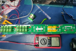
The primary focus of Libre Solar is solar electricity generation and storage, both for off-grid and grid-tied applications. Accordingly, the initial open source hardware projects are MPPT charge controllers and a battery management systems (BMS) for Lithium ion batteries.

An application example for the components is the Libre Solar Box which contains of the MPPT and the BMS as core components, lithium batteries (4 LiFePO cells) and a boxframe with connectors.

In the component list you find the necessary component for building up your DC energy system. It is modular and scalable. With the communication modules you can also monitor your energy data.

Unique features

There are lots of charge controllers on the market. So you might ask yourself why this one is special?

Extensible hardware

The PCB of the Libre Solar charge controller contains lots of interfaces which could be useful for applications not yet thought about. Especially the UEXT connector is useful to add features like displays, wireless communication, etc.

Creativity by software

Though the primary function of the charge controller is to charge a battery using solar panels, the hardware behind the charge controller is just a high-power DC/DC buck converter. With some tiny software changes it can be used for numerous other applications.

Some examples:

  • Small wind turbines with AC generators can be easily connected to the charge controller using some diodes for rectification. Now you can develop a Maximum Power Point Tracking algorithm for your wind turbine.

  • As a synchronous buck converter, the DCDC power stage can be changed into a boost converter by software. In this case, current flow goes from the battery output to the solar input. This feature can be used to charge an electric bike battery pack with 36V nominal voltage using a 12V solar pannel. Sounds strange, but works and has been tested already. The 5V output is needed to switch on the bicycle battery (e.g. Bosch or Specialized).

Fully Open Source

Software and hardware are fully open source and can be used even for commercial applications. You are free to change whatever you want as long as you publish your changes and contribute to the open source hardware community.

Hard facts - MPPT charger

If you want to know the core specifications…

  • Maximum Power Point Tracking (MPPT)
  • 12V or 24V battery output
  • 20A peak charging current
  • 55V max PV input
  • 32bit ARM MCU (STM32)
  • CAN communication interface with standard RJ45 jacks (CANopen pinout)
  • USB interface for firmware update and serial monitor
  • Expandable via Olimex Universal Extension Connector (UEXT) featuring I2C, Serial and SPI interface (e.g. used for display, WIFI communication, etc.)
  • Built-in protection:
    • Overvoltage
    • Undervoltage
    • Overcurrent
    • PV short circuit
    • PV reverse polarity (for max. module open circuit voltage of around 40V)
    • Battery reverse polarity (destructive, fuse is blown)

Hard facts - BMS

  • 3 Up to 15 Li-ion cells (e.g. LiFePO4)
  • 50A max. current
  • MCU: STM32
  • CAN communication inteface
  • UEXT connector for feature extension
  • High-side switches using new TI BQ76200
  • Possibility of pre-charging the power bus before switching on the battery.
  • Balancing current approx. 150 mA

View all 8 components

View all 4 project logs

Enjoy this project?

Share

Discussions

Gravis wrote 08/24/2022 at 12:44 point

Just FYI, your website (https://libre.solar) doesn't work AT ALL without cookies. It shows up as a blank white page.  This is a very poor practice.

  Are you sure? yes | no

Adam Quantrill wrote 10/27/2020 at 21:46 point

What are you plans for the mains inverter? With sync for feed-in? My use case is approx a 1kWh battery as backup for mains, and most of the solar feeding into the grid. I will have a quick switchover isolator to avoid feeding mains into the grid on a power cut. The mains backup is intended to keep just a few appliances alive, such as the central heating electrical power, and lighting. So the invertor would ideally be able to be used both in sync mode and free-running.

  Are you sure? yes | no

Lightning Phil wrote 10/24/2020 at 21:27 point

Attempted to build a similar system a few years ago - bit rushed as wanted to finish it within a week before installing it in the families summer place in central Finland.  In short, it caught fire so gave up and purchased a commercial unit.

The problem was the firing of the MOSFETs in the synchronous buck converter occurred at the wrong time and allowed current from the load (a car battery) to flow back through them.  They liked this so much they glowed red with happiness.

Larger goals of the project were to have various outputs that would respond to available power, allowing excess to run a cool box.  Not just wait till batteries are charged and then run the cool box, but if early in the day and charging is high - predict that full charge will be made and turn on cool box early.  Direct correlation between excellent solar days and demand for cool beer...

  Are you sure? yes | no

Michael LaVigne wrote 08/13/2020 at 14:07 point

Interesting project- i love the idea of having tighter control over the whole DC system.  Adding something like lumencache for lighting (or an OS/DIY version) would give even more system-wide control.  

Any reason you went with CAN-bus?  is the system going to be master-less?  I only ask because Modbus (over RS485) is more standard for building automation, and is easier to troubleshoot and requires less hardware (just a UART on the processor, and a transceiver chip with a few passives for protection).  Best I can tell, the only downside of RS485-Modbus vs CANbus is that it has a master-slave topology...

  Are you sure? yes | no

Martin Jäger wrote 08/14/2020 at 11:12 point

Yeah, the master-less operation is exactly the reason for CAN bus. We want the system to be plug & play, so that every device could e.g. communicate its maximum voltage via the bus.

  Are you sure? yes | no

Norbert Heinz wrote 07/24/2020 at 18:22 point

Hallo Michel,

war schön dein Projekt über die Mentor-Session mit Sophi näher kennenzulernen. Ist der CAN-Bus in der Lage den Batterie-Ladezustand der 12V Batterie in einem Auto auszulesen und über ein Solarpanel aufzuladen? Ich überlege, ein solches Panel auf dem Dach meines Taxis zu montieren, dazu würde LibreSolar gut passen.

  Are you sure? yes | no

Michel wrote 07/27/2020 at 14:46 point

Hallo Norbert, Vielen Dank hat mich ebenfalls sehr gefreut Deine Projekte näher kennenzulernen.

Ich gehe davon aus, dass Du Dich auf eine 12V Blei-Batterie in deinem Auto beziehst. In diesem Fall kann die Batterie direkt an den Laderegler angeschlossen und damit der Ladezustand vom Laderegler berechnet werden.

Ansonsten kannst du nochmal kurz die CAN Schnittstelle in deinem Auto näher beschreiben.

Viele Grüße

  Are you sure? yes | no

Norbert Heinz wrote 07/27/2020 at 14:53 point

Jawohl, meine ollen Autos haben noch die guten alten 12V Bleiakkus ;-) dann passt das von der Seite. Mit dem CAN-Bus in dem Taxi muss ich mich selber erst einmal auseinandersetzen sowas kenn ich von meinen 2CVs nicht.

Danke für die Antwort und Grüße zurück in den Norden!

  Are you sure? yes | no

Similar Projects

Does this project spark your interest?

Become a member to follow this project and never miss any updates