 Will Donaldson
Hardware overview
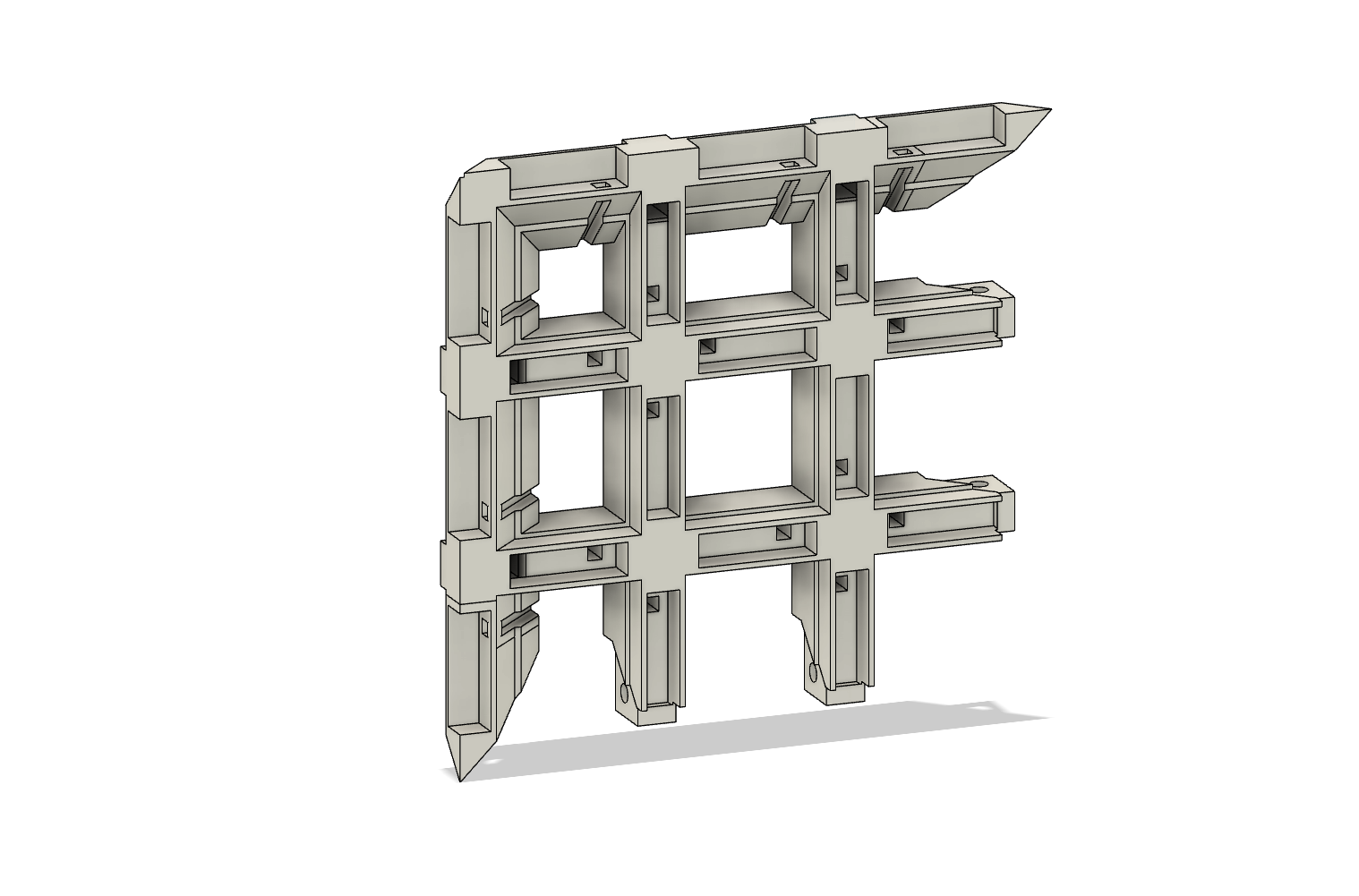
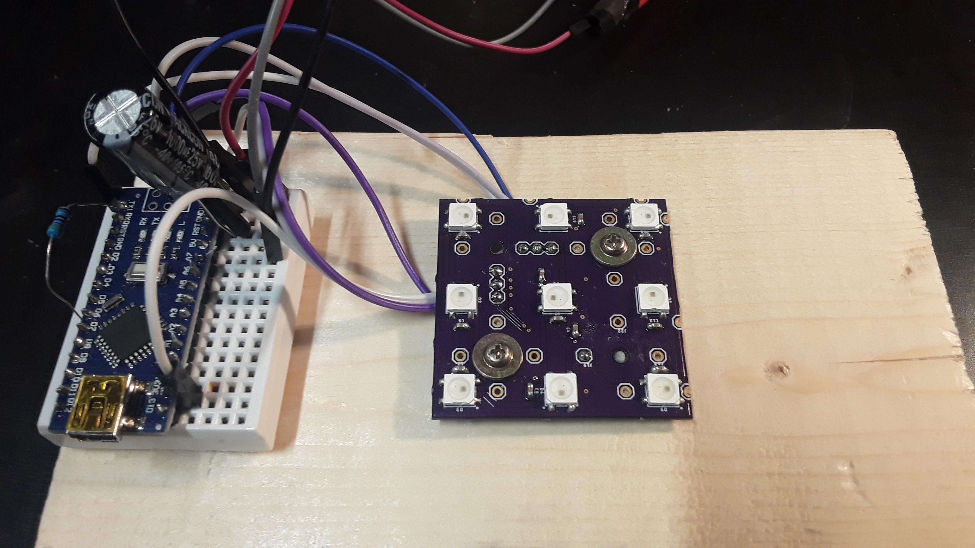
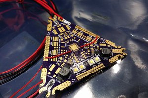
The cube is made of 6 identical* face pieces that are designed to interlock with each other; each face has 9 acrylic tiles for diffusing the LED light and 18 brass square rods that act as capacitive touch sensors. Behind each of these faces is a circuit board with 9 different RGB addressable LEDs. The circuit design is discussed further in the next section.
The acrylic tiles are 3.175mm thick with a side length of 15.5mm; they are supported in the 3D printed frame through a friction press and a small 0.5mm lip in the 3D printed frame to ensure they are not pushed in too deep. The edge acrylic pieces have their sides tapered at 45 degrees (see pictures), the current design utilizes friction to hold them in place but they could be glued in place too.
The brass square rods are 3.175 x 3.175 x 15.5mm and also held in place through friction. Small channels are cut in the 3D printed frame for connecting the brass rods to the PCB via wires.
Inside the cube, the six cube-face circuit boards are connected to a seventh control board and communicate via an I2C bus. Behind the circuit boards is a smaller cube-shaped void, in this void a lithium-ion battery is placed.
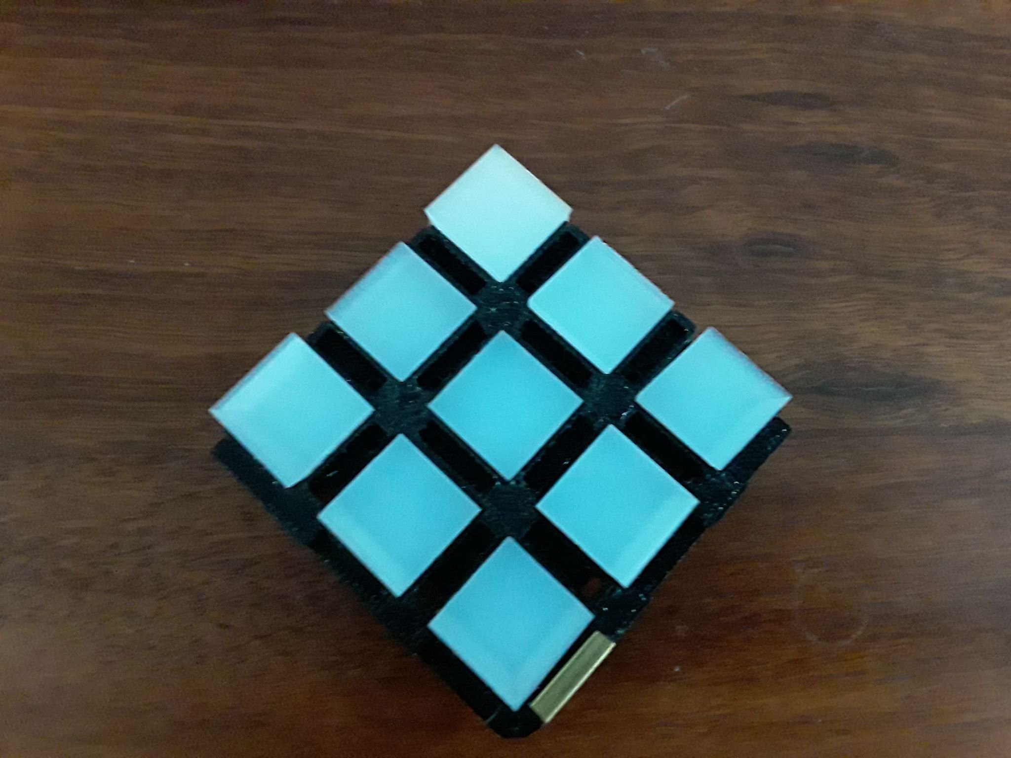
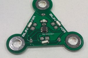
In the first image note the small channels that connect the PCB board behind the frame to the brass capacitive touch sensors at the front of the frame. In the second image you can see a the 3D printed model with 9 acrylic tiles and 1 of the 18 brass capacitive touch sensors.
*modification is made to one of the faces to allow for a battery charging port
Electrical overview
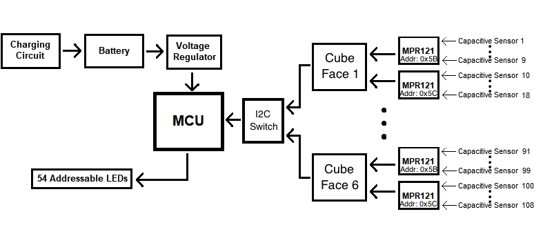
See block circuit diagram in the pictures for a broad overview of the circuit
Each of the 3D printed frames has a two-sided circuit board mounted on it. On one side will be 9 RGB addressable LEDs for displaying the colour of the Rubik's cube tiles. The 18 brass capacitive touch sensors will be connected to the circuit board via short wires that fit into the channels cut out of the 3D printed frame, these 18 signal lines will be split into two groups running to one of two MPR121 chips. The MPR121 is a 12 channel capacitive touch chip with four I2C addresses (datasheet link). Due to the limited number of I2C addresses and the need for 12 MPR121 chips (2 for each of the 6 cube faces) a central I2C switch is included for cycling through each of the 6 circuit boards. This central I2C switch is mounted on a seventh control board, that is positioned in the central void of the cube, next to the battery. In addition to controlling the I2C communication it will also have a microcontroller, voltage regulator, and charge control circuits.
Software overview
The microcontroller will be responsible for periodically collecting the binary state of the 108 capacitive touch sensors (touched/not touched). If a row/column of capacitive touch sensors on any of the faces are touch one after the other and within a certain time threshold a “swipe” will be registered and the LEDs will change colour to reflect a ‘rotation’ of the cube. Touches that are detected that are not part of a “swipe” will be ignored since in order to hold the cube the user will inevitably be making contact with some of the capacitive touch sensors.
Existing Problems
There are two noteworthy shortcomings in the current proof-of-concept design: cube size and battery life. The current design has a side length of 65.3mm whereas the standard Rubik's cube has a side length of 57mm. In hindsight, I could have made a design that adheres to this measurement but I have already cut all the acrylic pieces by hand (most of which are tapered at 45 degrees on one or two of their faces), and I would rather not go through this laborious task again. After all this is merely a fun, proof-of-concept project.
Secondly, the short battery life (currently) prevents this project from being little more than a novelty. I am using a 3.7V 1800mAh lithium-ion battery; this was...
Read more »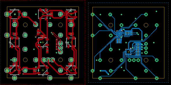
 Gee Bartlett
 DIY GUY Chris
 slisgrinder