 Will Donaldson
This build log documents the PCB design of the 6 identical boards for each of the 6 cube faces. Recall from the 'Project Details' section (above) that there will be a 7th central PCB that has a microcontroller and is responsible for power regulation. Each of the 6 cube-face boards have the following features:
- 9 WS2812B LEDs (datasheet)
- 2 MPR121 chips (datasheet)
- 18 through-holes for connecting brass capacitive touch sensors
- 4 mounting holes (M2 mounting bolts)
- Additional through-holes for inter-PCB cabling
Below are images of the top and bottom PCB traces (red and blue lines, respectively). Note that some traces appear to be touching, this is not the case; I was merely sloppy and used a screenshot then poorly compressed the image. I will not be publishing any of the design files until the project is finalized.
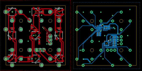
The topside has the 9 LEDs chained together and can then be connected to the neighbouring board, once connected there will be a continuous strip of 54 addressable LEDs instead of 6 segments of 9 LEDs. Matrix rotations will be used for calculations in the software.
The bottom side has two 12-channel MPR121 chips with different I2C addresses of 0x5B and 0x5C. These chips were chosen as the I2C protocol allows for easily checking the state of individual capacitive touch sensors as opposed to a convoluted multiplexing network. This will make developing the software that monitors for "swipes" easier (and faster). I unfortunately could not source an alternative 18-channel capacitive touch chip with I2C. If you wish to replicate this project please be aware that this chip is a legacy device and not recommended for new designs, however since this is a hobby project and not something I plan to make commercially this was not a concern (available for purchase here-as of Oct. 2020). Furthermore, on a personal level, I wanted to practice reflow soldering with a QFN chip (quad-flat no-leads).
Note that 6 of the 18 through-holes for connecting the brass capacitive touch sensors are on the edge of the board as castellated holes. While not my first preference this was the only way I could devise that connected the PCB to the corner capacitive touch sensors without interfering or block the light from the LEDs.
The PCBs were manufactured by OSH Park (not-sponsored).
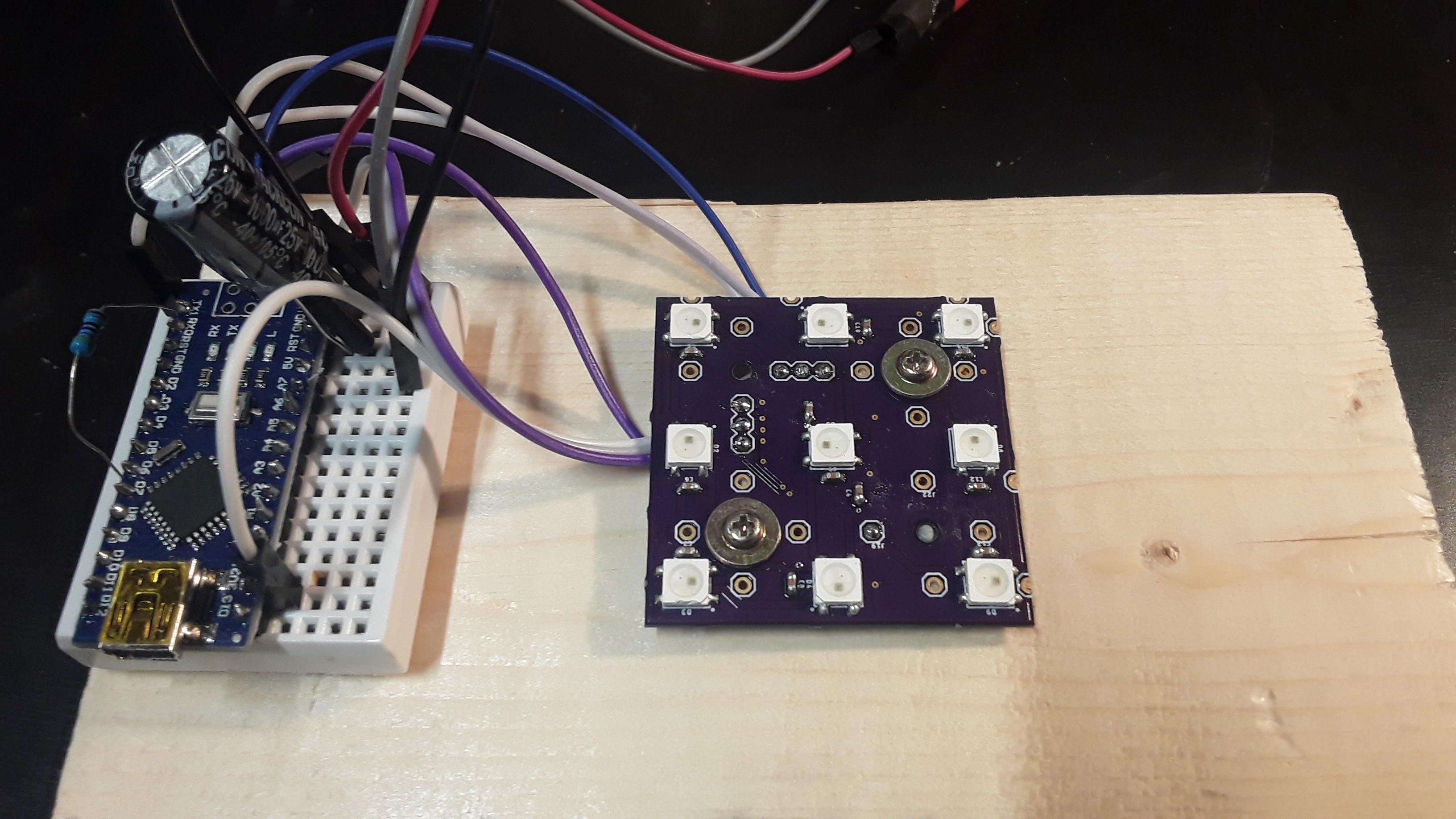
Assembling the PCBs was done with reflow soldering using a hot air gun. I would recommend doing the bottom side first to get the QFN packages out of the way. Below is an image of the assembled board mounted on a test rig.
Discussions
Become a Hackaday.io Member
Create an account to leave a comment. Already have an account? Log In.