 James Wilson
The design goal is produce a LED array that can be a good substitute for a IN-13 Nixie tube, and easy to control from a microcontroller. After looking at available options, I decided on these design elements: 0603 LEDs and 16-bit constant-current shift registers.
0603 LEDs can be spaced 1 mm apart for high resolution, and they are plentiful and cheap. While 0402 or even 0201 parts would allow higher resolution, they're a bit more expensive.
TI and ST both make a line of constant-current LED drivers with shift-register multiple outputs. More channels = fewer parts = generally better, but many of the 24- and 48-channel chips are expensive and have features that are unneeded and complicated. In fact, many of these drivers blur the lines between "dumb" shift registers and "smart" microcontrollers: some of them have multiple configuration registers to adjust the current, PWM counters for each channel, and diagnostic output. All of this is controlled by sending special serial sequences on the data and latch pins. The need to send bespoke synchronized data sequences across multiple lines make these features hard to use, and somewhat more appropriate for FPGA control than microcontrollers. After some searching, I found a 16-bit driver that was suitably dumb (and cheap): the TI 59283. It lacks current gain control (meaning the output current is fixed by the choice of a resistor) and individual LED dimming, but supports global dimming by PWMing the output enable line. A second consideration was the chip package. Most of these chips are available in leaded packages (SO and SSOP) that are a bit large. Something in a QFN would be better, to keep the board size small. Fortunately, the 59283 is available in a QFN-24 package.
The target board size should be no more than 1" wide and about 150mm long (about the length of the IN-13; the actual display length is less). Allowing some space for connectors and plumbing, 128 LEDs, using 8 shift registers, was the natural choice. The board should have a small (5 mm or so) border so a spacer and diffuser can be glued on.
I'd like to share this design as it fills a hole not available from hobbyist LED arrays, so breadboard headers are the universal connector to use, but I also want a JST PA connector on the rear side for nicer board-to-board and enclosure integration.
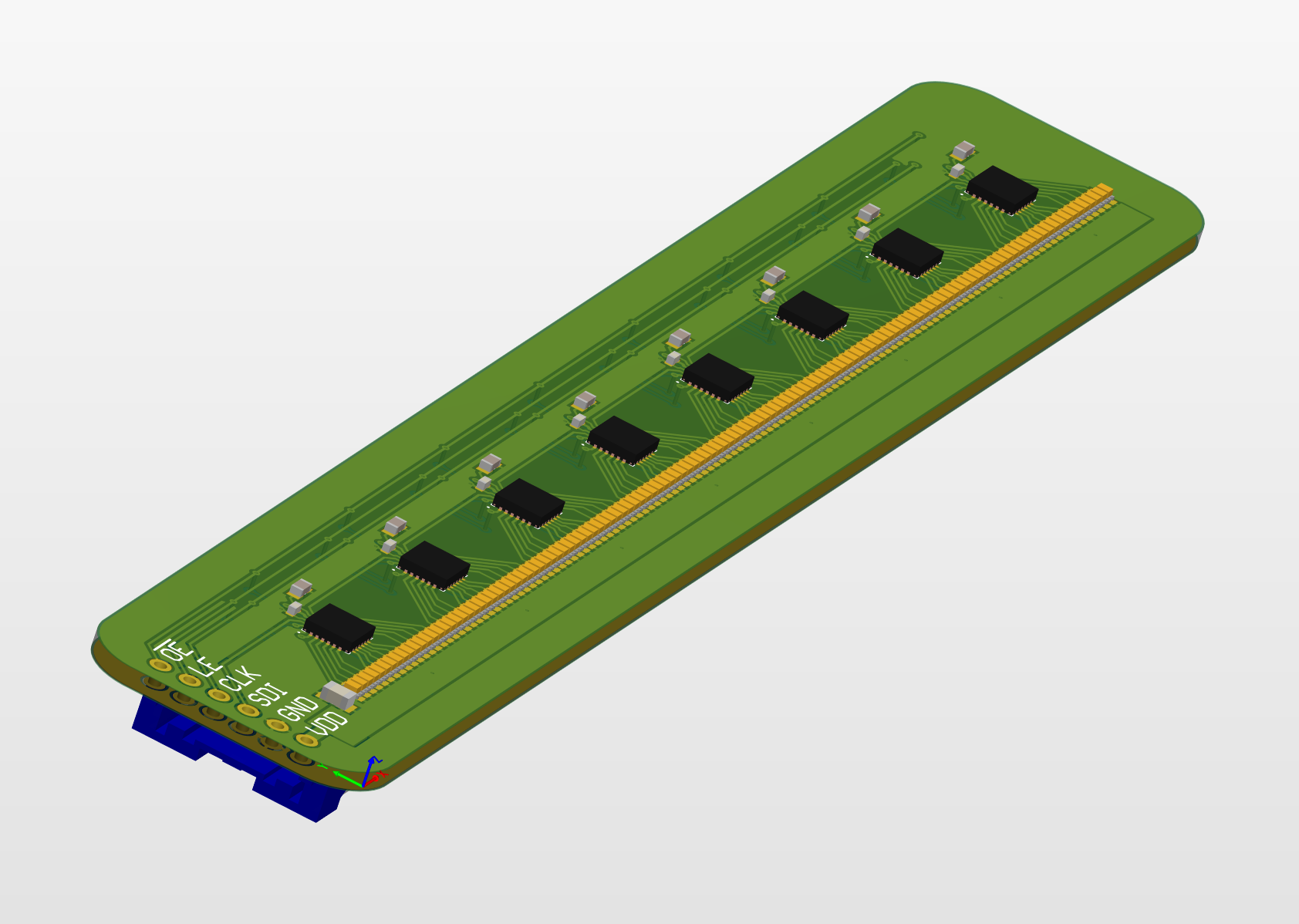
My plan is get JLCPCB to assemble the board with the LEDs and passives. They do not stock the 59283, so I will need to rework it manually. Here is a 3D model of the board design. Each shift register has a 11 kΩ resistor that sets the output current to 5 mA (plenty bright). A 4.7 µF capacitor provides some bulk decoupling for the LEDs when they are turned on or off in unison by PWM. LED color is a personal choice, but I went with orange to mimic the color of Nixies, and it's a good color regardless of viewing conditions.
Discussions
Become a Hackaday.io Member
Create an account to leave a comment. Already have an account? Log In.