Having previously decided which, and how many, LEDS we are going to use. It is now time to design a driver to power them. This post goes through the calculations needed to design the circuit, the following post gives some recommendations on designing the PCB.
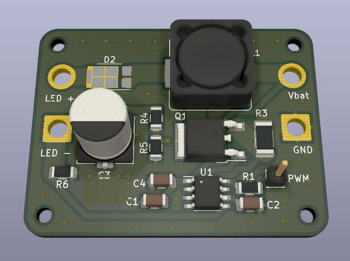
Here is the final product.
Choosing the main driver IC
According to our calculations, to achieve max brightness we need a driver capable of providing 1Amp @ 26.4V (the combined forward voltage of 6 ls). Also, since our power source is a 3S Lipo battery, we need a BOOST driver, as the voltage provided by the battery 11.1v will need to be stepped up to the voltage required by the LEDs.
We chose the AL8553 because it has an external MOSFET, It's small, inexpensive, has good integrated over-current and over-voltage protections, supports dimming control through PWM, and comes in a leaded IC package (important for ease of soldering).
Designing the Circuit
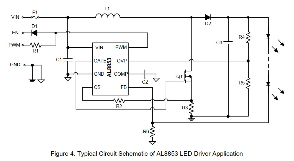
Designing switching converters is hard. Thankfully, the datasheet has all the instructions and equations required. Now, we only need to calculate the value of the components in the example schematics.
We are going to number the equations with the same numbers as the datasheet, so you can follow along if you want.
L1:
This is the main switching inductor of the circuit. Here's we need to calculate its Inductance and the Maximum Current it will handle. Here are the variables we know:
- Output Voltage: 26.4V
- Led Current: 900mA (To run the Leds at a little less than maximum power)
- Input Voltage: 11.1V (Nominal of a 3s Lipo battery)
- Efficiency η: 0.85 (Standard efficiency of BOOST drivers)
- Ripple Current Rate γ: 0.5 (Datasheet, p.10 suggest between 0.3 and 0.5)
- Switching Frequency f: 120Khz (According to datasheet p.4 table)
First we calculate the average current through the inductor:
Then the peak-to-peak variation of that current.
Now we know the maximum peak current that the inductor will need to withstand at any given point (And we can oversize it by 20% just to be sure):
Finally, we can calculate the inductance value like so:
Ok, so we know the inductor needs to be L1 = 43uH @ 3.8 Amps.
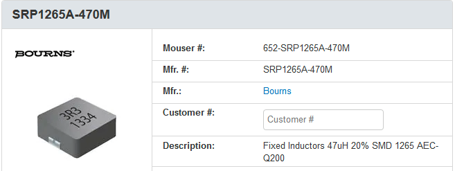
Looking through Mouser, I found this one that I liked SRP1265A-470M (Link to mouser listing) from Bourns it's the exact same inductance value, but 47uH is close enough..
R6:
This resistor controls how much current goes to the LEDs. And, assuming a LED current of 900mA can be calculated with the following formula:
This resistor is in the path of the led current, so it's mportant to double check his power dissipation.
Therefore R6 = 0.222ohm @ 180mW
or if you prefer to run the LEDs at 1Amp, R6 = 0.2ohm @ 200mW
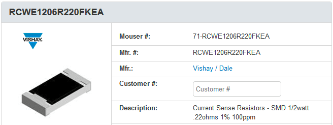
I liked the RCWE1206R220FKEA for the 0.222ohm, and the RCWE1206R200FKEA for 0.2ohm. They are high precision, and are rated for 0.5W of power.
R3:
This resistor controls the over-current protection trigger. The datasheet recommends setting this trigger point using 30% more than the maximum current expected by the circuit. Which happens to be the maximum peak current of L1, at the lowest expected Vin: 9v (The lowest safe voltage of a 3s lipo battery).
Using the equations from L1, we can calculate this peak current.
Finally, we over-size it by 30% to find the Over-Current Protection Current.
And now R3 is equal to:
We can also calculate the power consumed, just as we did with R6. Which means
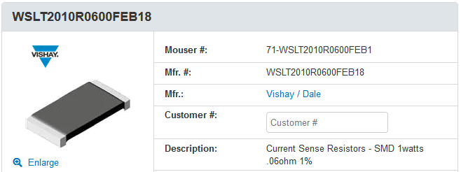
R3 = 60m @ 0.54W
That's a lot of heat for an SMD resistor, So it is important to size it appropriatly. I found the WSLT2010R0600FEB18 to be adequate for the job.
R4 and R5:
This resistors are used in a voltage divider that sets the trigger for the over-voltage protection. Which is good to have in case the LEDs get accidentally disconnected during operation and leave the driver with an open-circuit. Mercifully, they have a fairly easy equation.
First, the datasheets suggests we define the Over-voltage threshold as 20% more than the nominal output voltage.
Now, the Relationship between R5 and R4 is given by.
Looking for a combination of standad value resistors that satisfies this ratio, I found a good pair with:
- R4 = 150K
- R5 = 10k
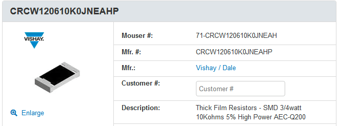
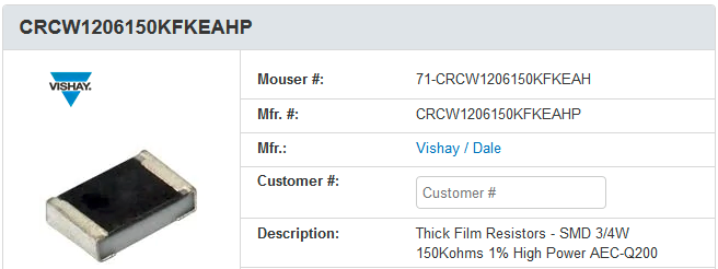
It is not an exact match, but it is close enough. These resistors don't need to dissipate a lot of heat, so it's critical which ones we choose. I liked these ones:
- R4 = CRCW1206150KFKEAHP
- R5 = CRCW120610K0JNEAHP
Q1:
This is the main switching MOSFET. It only has a handful of recommendations on over specifying the voltage and current withstood by the transistor, namely
- Vds = 38.4V (20% more than over-voltage threshold)
- Ids = 4.63Amp (20% more than the nominal peak current)
- Vgsth < 13V (The datasheet p.4 says the max gate trigger voltage the chip can generate is 13V)
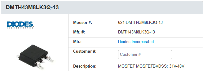
I searched around on Mouser and found the DMTH43M8LK3Q-13, which fits nicely with these recommendations.
D1:
This diode also only has a handful of recommendations. It should withstand the same voltage as the MOSFET and as much current as the LEDs. Also, I personally recommend a Schottky diode, because the less the Forward voltage of D1, the less heat it will need to dissipate, and the more efficient the circuit.
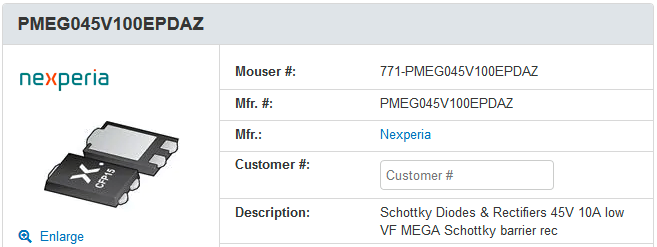
Here is a good candidate: PMEG045V100EPDAZ, it has a nice Vf: 0.3V, which was about as low as I could find for this forward current rating.
R2:
This resistor controls the Slope Compensation features of the AL8853. However, we are not using this feature in this design, so this resistor is not necessary.
R2 = 0ohm.
C3:
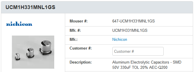
This is the output capacitor of the driver, it helps stabilize the output current. There are actually no suggestions of how to choose it. So, I took some inspiraton from some Texas Instrument Application Notes of high power LED drivers, and set it to:
C3 = 330uF @ 50V
I suggest this one UCM1H331MNL1GS. It has a high enough capacitance, and can safely withstand the output voltage.
C1:
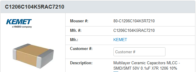
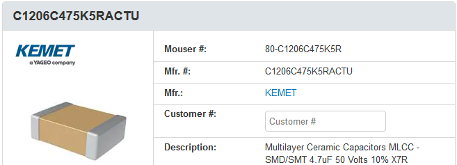
This is the Input decoupling capacitor, Also has no indications of how to select it. In this case we decide to use 2 capacitors in parallel:
- C1 = 4.7uF
- C4 = 100nF
These ones will work for this case: C1206C475K5RACTU, and C1206C104K5RAC7210
C2:
Funnily enough there is no mention anywhere of why this capacitor exists, or what it does. So I just chose this value and hoped it would work.
C2 = 100nF
I suggest using the same as C4.
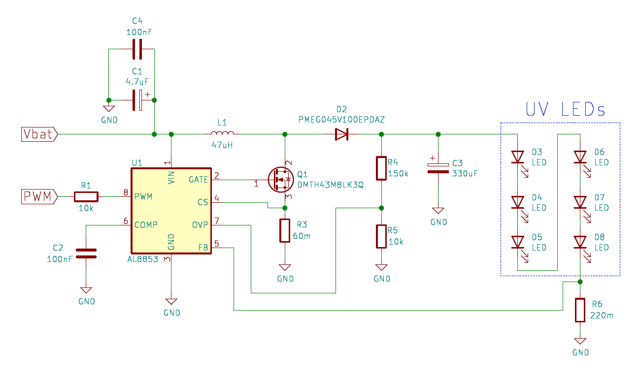
Complete circuit schematic
Finally, we can put all this together, to get the full schematic

In the next post, we will go into more details on how to design the PCB for this circuit.
 Said Alvarado Marin
Discussions
Become a Hackaday.io Member
Create an account to leave a comment. Already have an account? Log In.