 bobgreenwade
Intro
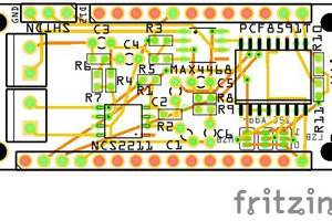
This Shield brings sound in through a Maxim MAX4468 microphone pre-amp, sends it straight to a Spin Semiconductor FV-1, and then out through an ON Semiconductor NCS2211 speaker amplifier.
Purpose
There are several applications one could use this Shield for in an Arduino project:
- Wearable/portable voice changer
- Musical instrument effects unit
- Portable personal stereo
I'm sure others can come up with other ideas, including as just one element in a much larger and more complex project. (The wearable voice changer is my pet project, but I also plan to make this Shield as broadly applicable as I can.)
Details
The FV-1's settings are controlled via a Maxim MAX11312 I2C controller. That same controller also operates an ON Semiconductor FSA2211 data switch, which serves as an electronic DPDT switch. The same signal that operates the switch changes the 24LC32 EEPROM chip from its normal connection to the FV-1, storing "external" programs as a Read-only chip, to a Write-capable chip connected directly to the I2C bus so those external programs can be loaded onto it. The switch connects the EEPROM to the FV-1 when in Read-Only mode, or to the main I2C bus when in Write-Capable mode.
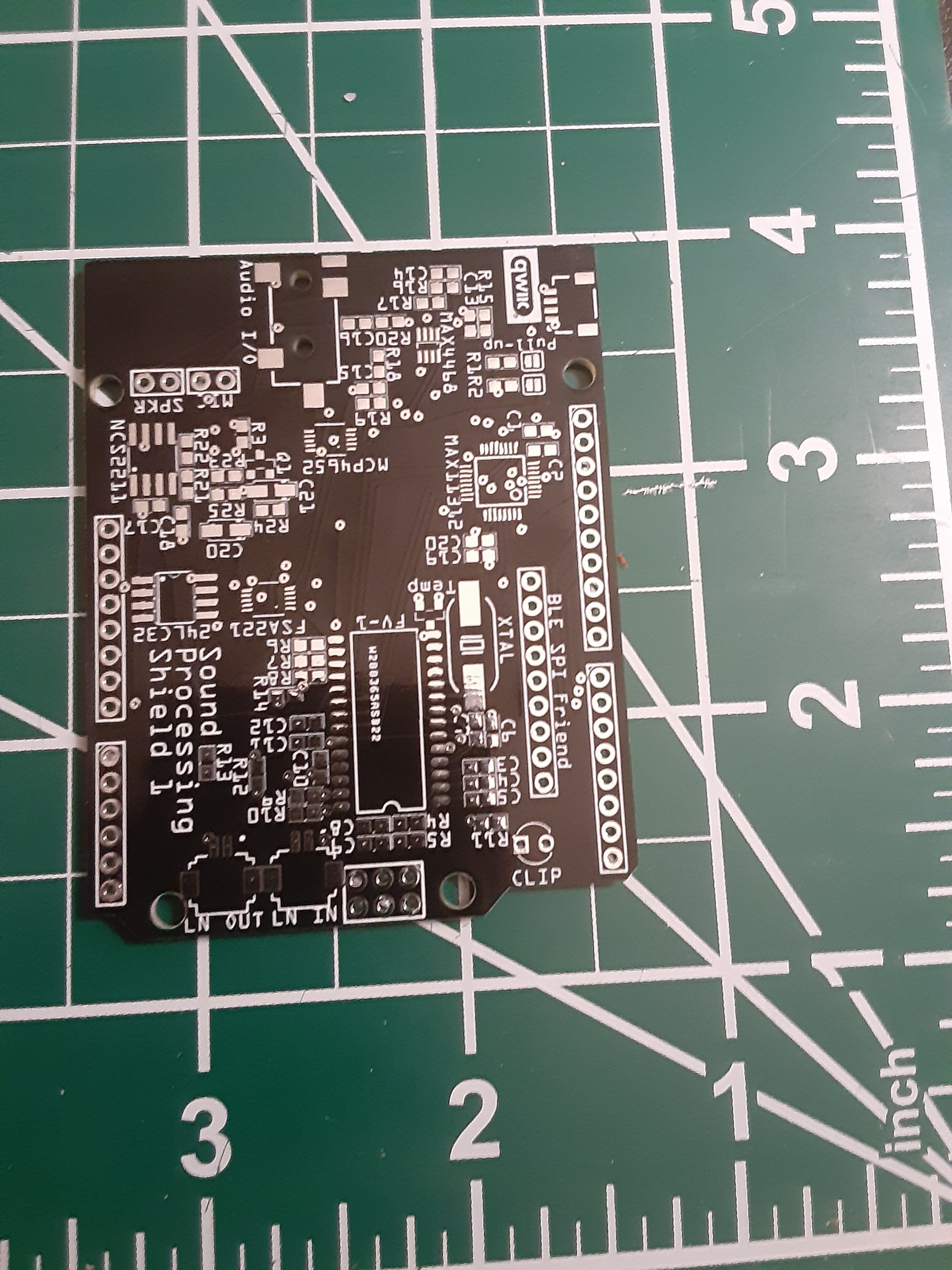
There's also an option for adding a Bluetooth Low Energy (BLE) capability to a project, via Adafruit's BLE SPI Friend. The header for this connects the Friend's pins to the GPIO pins used in the breakout's provided sample code (as shown in the Wiring section of its tutorial; these are 4, 7, 8, 11, 12, and 13). If you don't want to use the Friend for any reason, just don't include it; those GPIO pins will then be left open, so other Shields can use them.
Besides the GPIO pins mentioned in the preceding paragraph, the only pins used by this Shield are those that can be easily shared with other Shields: Power (both 3.3V and 5V), Ground, ARef (analog reference), and the I2C pins.
One of the MAX11312's ports controls the MAX4468's Shutdown function; another is connected to the Friend's DFU (Device Firmware Update) pin; another controls whether the EEPROM is Read-Only or Write-Capable. All the MAX11312's other ports connect to the FV-1 (including one to read the CLIP function and another intercepting the mike input).
A Microchip MCP4652-503 dual 50kΩ digital rheostat -- with a separate I2C address -- controls the mike and speaker volume.
There are three ways that the audio signal can leave the board. The "normal" way is through a 3.5mm TRRS audio jack (the four leads carrying IN+, OUT-, OUT+, and IN- respectively). In case the user is building something with the mike and speaker in the same enclosure as the Shield, there's also a pair of two-lead right-angle headers to connect them.
Finally, should the user want to process a signal through more than one FV-1, a pair of connectors allow the user to send the output of one directly to the input of the next. While the MAX11312 is capable of up to eight I2C addresses, the selection on this board is limited to four; it's highly unlikely anyone will want more than two.
(For those who might want to connect the mike and speaker through separate mono audio jacks or bare-wire connectors, a separate version of this will feature those options in place of the TRRS jack and right-angle headers. That's why the board is labeled Sound Processing Shield 1; the other one will be Sound Processing Shield 2. That will be the only difference, so all sketches should work equally well with both.)
As a bonus, the board also has three Qwiic connectors... because, well, you can never have too many Qwiic connectors.
Usage
This Shield is designed to be usable with either an electret or piezoelectric microphone. By default, it's set up for an electret; to use it with a piezo (without it sounding tinny), just switch the "Mic Type" solder jumper on the underside from "E" to "P."
The 10kΩ Pull-Up resistors are connected by default. If you have other I2C boards with their own Pull-Up resistors, you may...
Read more »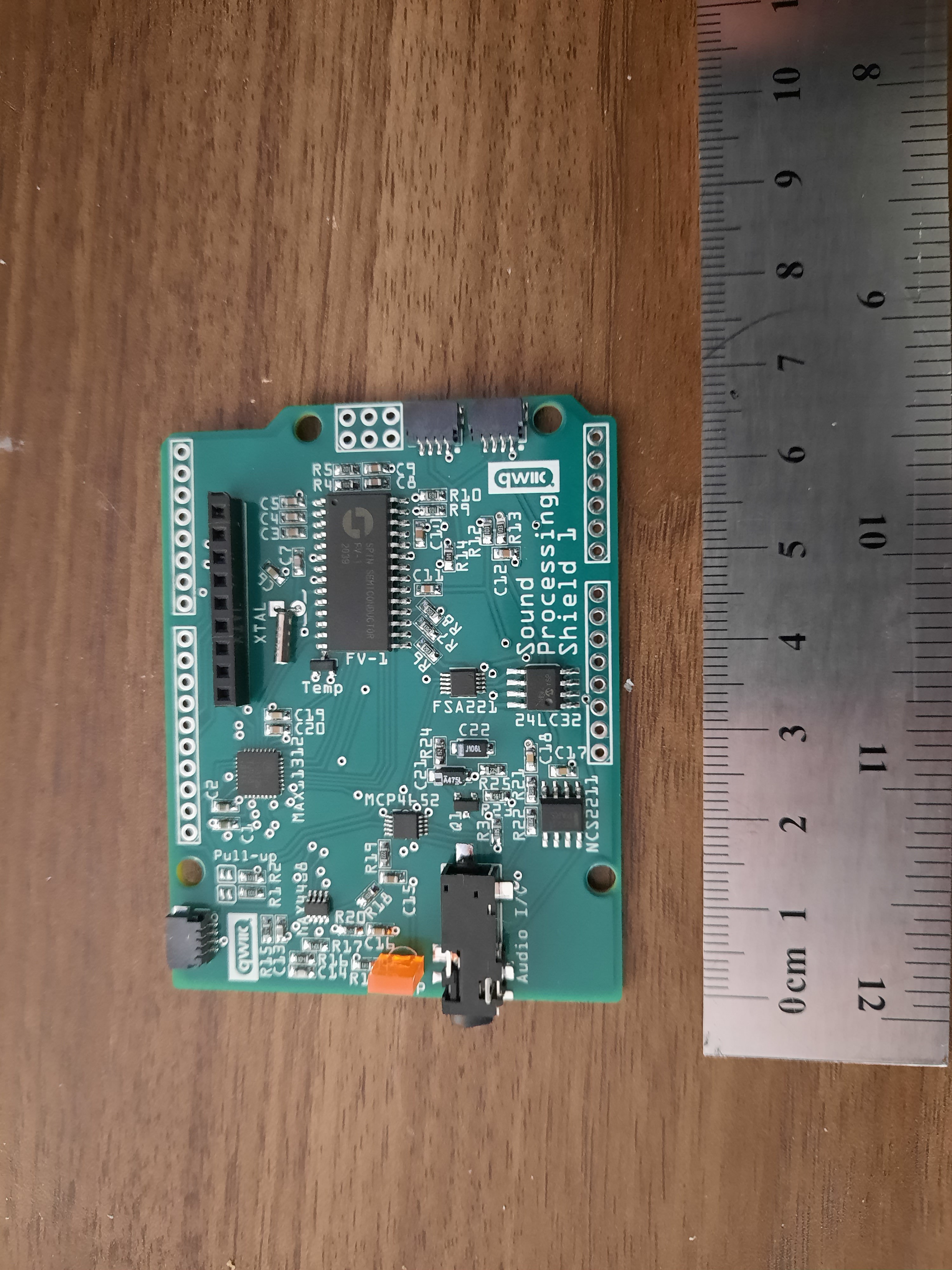

 John Adams
At this time there are still two ports available on the MAX11312, and space for a few more ICs if I want to add them, so if anyone has any suggestions for functions or capabilities to add to this Shield, by all means feel free to post them.