Close
0%
0%

Color ASCII Terminal

ASCII terminal supporting VGA 640x480 with 256 colors and USB keyboard

Similar projects worth following
This project is the evolution of Geoff's ASCII terminal. The objective is twofold. First is to create completely new board and firmware based on STM32 with color VGA and USB keyboard support that implements terminal compatible with historic VTs and modern XTerm. The second is to backport the new terminal code to the PIC32-based Geoff's board sold on Tindie to expand its capabilities.

Following is the list of specific capabilities planned for Color ASCII Terminal.

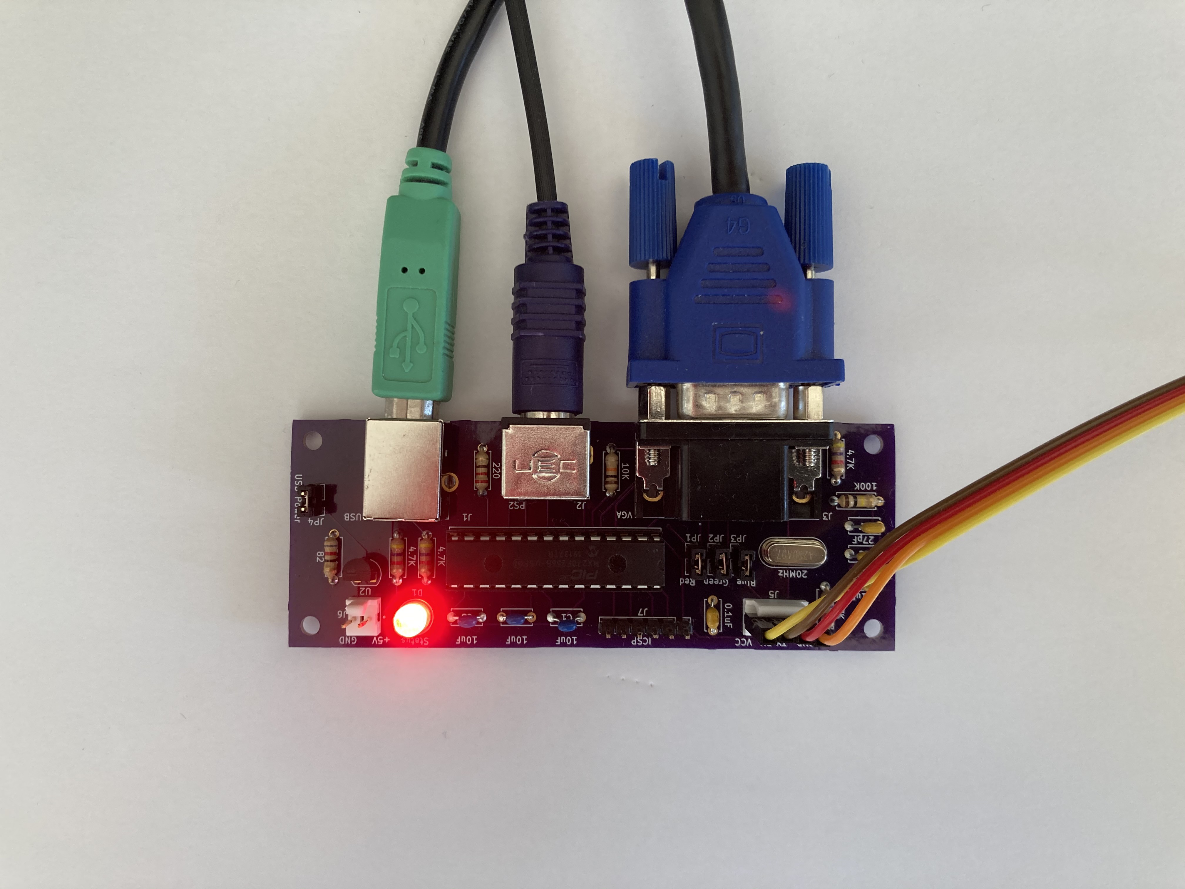
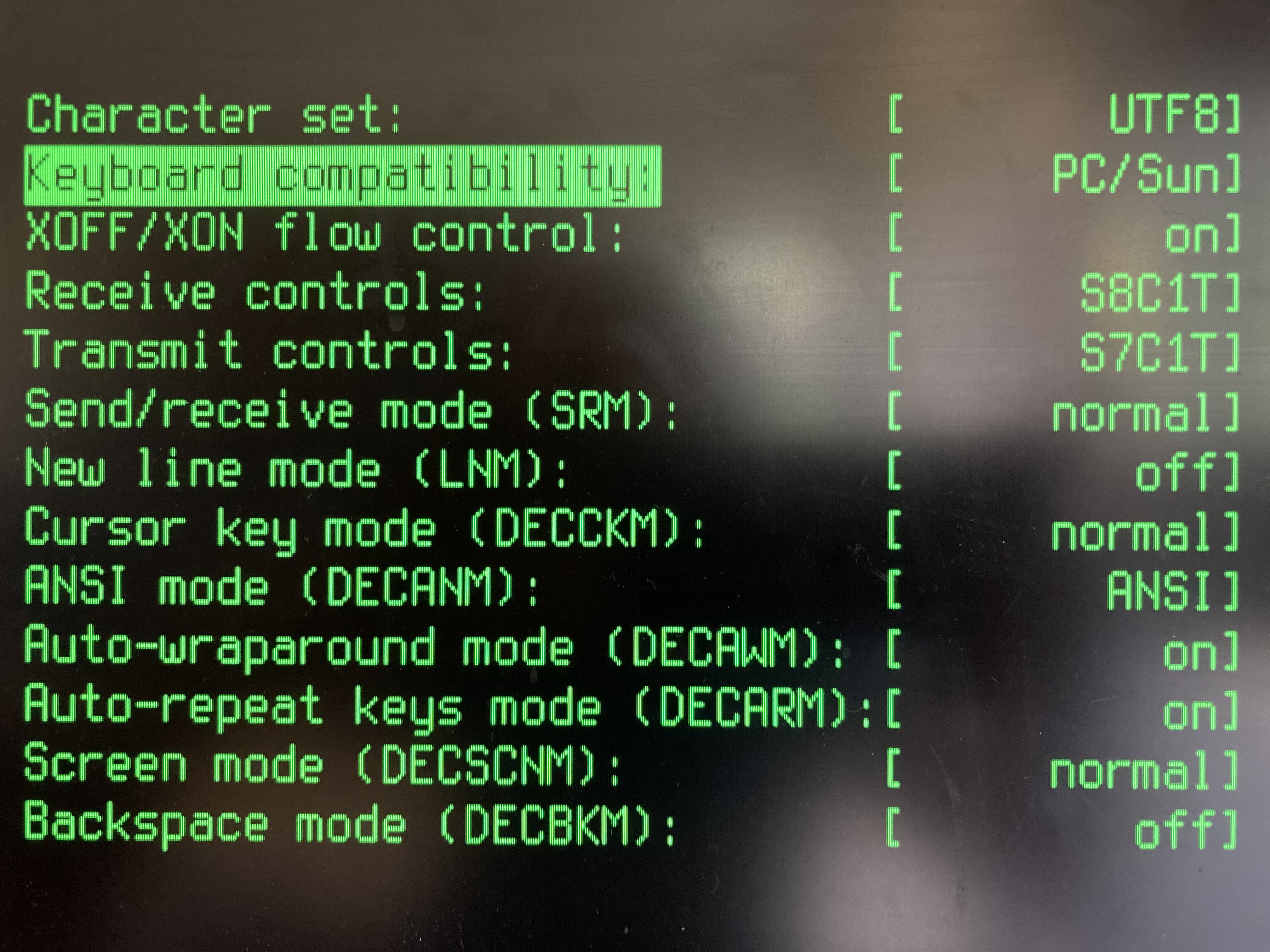
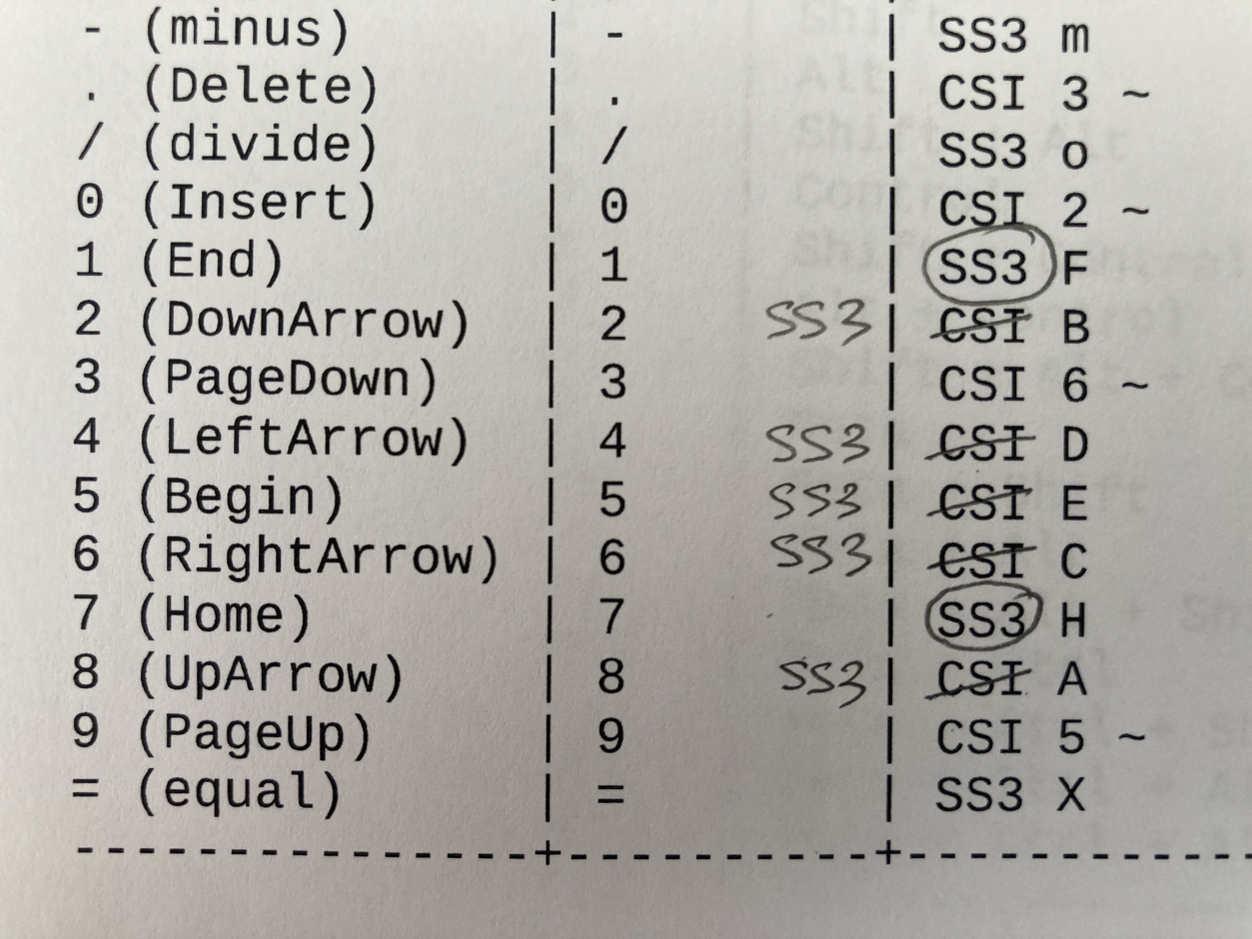
  • XTerm compatibility (tested with vttest and wraptest)
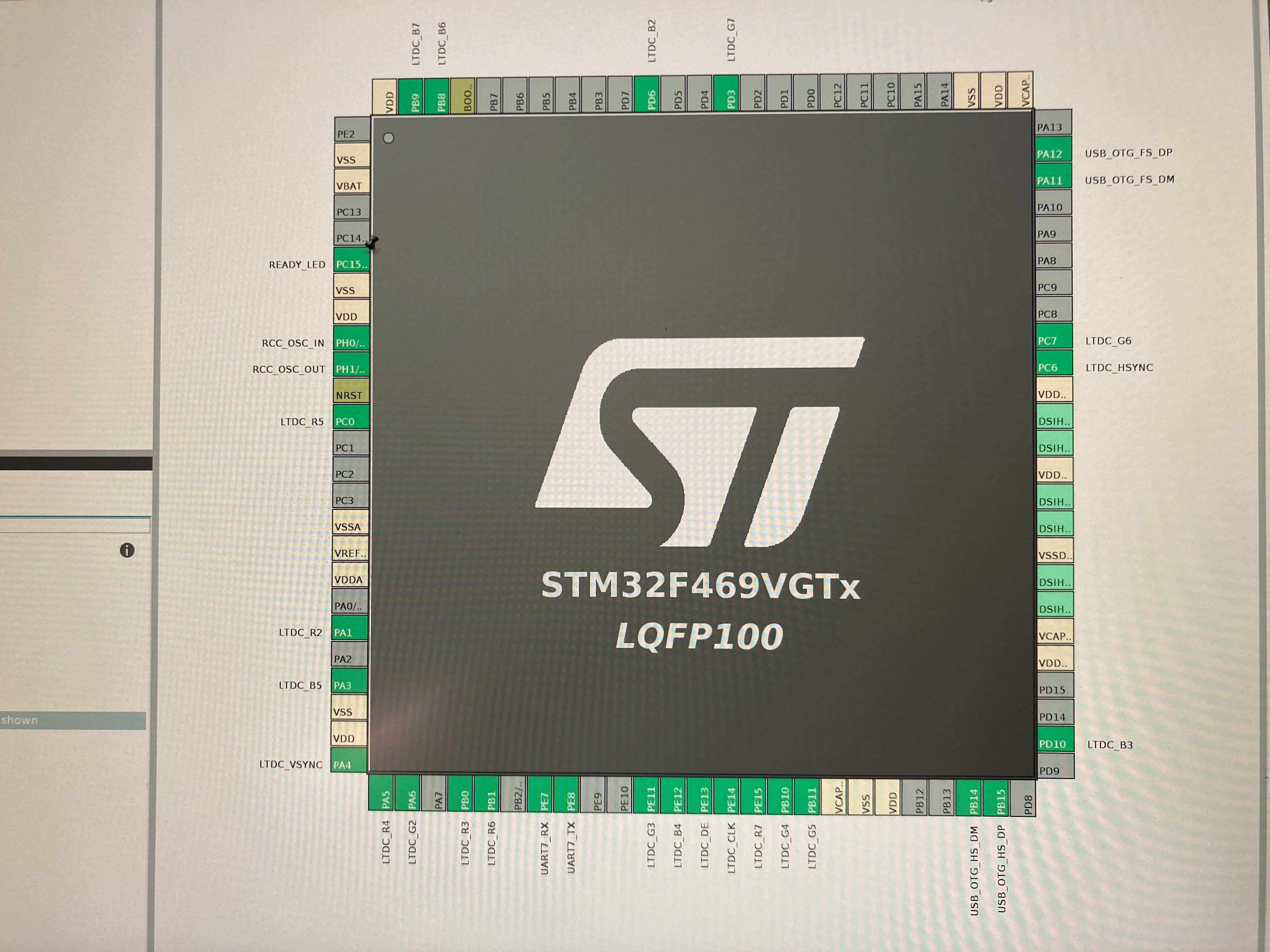
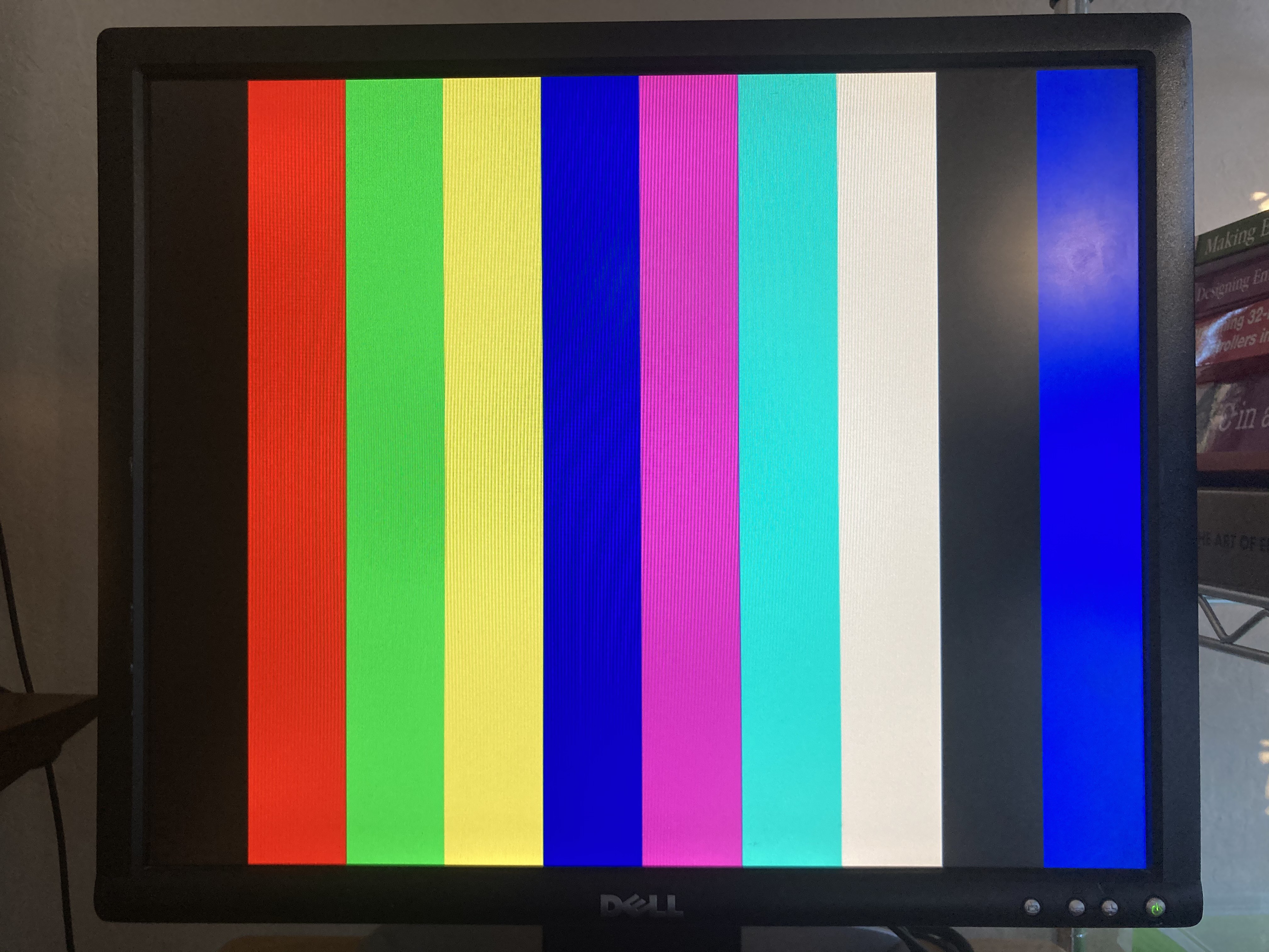
  • VGA 640x480 with 25MHz pixel clock
  • 24/30 lines and 80 columns
  • 256 ANSI colors**
  • Bold, underlined and strike-through fonts
  • Blinking and inverted visual attributes
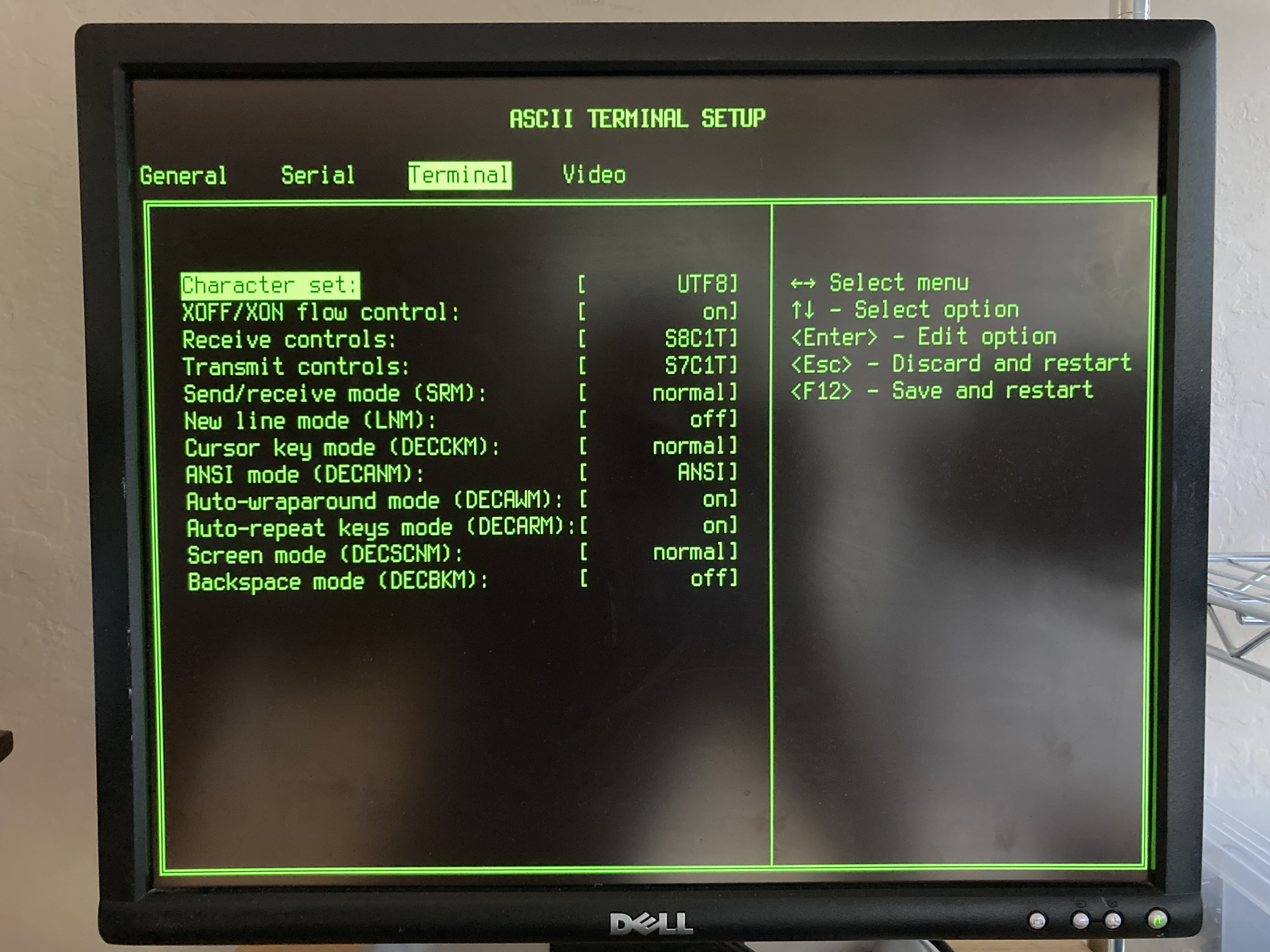
  • UTF8 with Unicode font
  • ISO 8859 and IBM PC 437 code pages as alternatives to UTF8
  • DEC graphic characters
  • Full range of baud rates: 110-921600
  • 8-bit and 7-bit control sequences
  • Scroll-lock and XON/XOFF flow control
  • USB keyboard*
  • Keyboard auto-repeat

* Capabilities won't be available on PIC32-based board

** Color-to-monochrome transformation on PIC32-based board

  • Bring-up time!

    Peter Hizalev11/15/2020 at 03:47 0 comments

    Successfully brought up the board despite some solder bridges in LQFP. Need to practice my SMT zen.

  • Color ASCII Terminal boards arrived!

    Peter Hizalev09/25/2020 at 16:41 0 comments

    Time for stencilling and baking.

  • The version 3 of PIC32 board is here!

    Peter Hizalev09/18/2020 at 18:06 0 comments

    Onto final testing before stocking up the Tindie store.

  • VT220 and PC/Sun keyboards

    Peter Hizalev08/08/2020 at 17:07 0 comments

    Apparently there are two standards for control sequences generated by the numeric and editing (INSERT, HOME PAGEUP, etc) keypads. First is the standard mimicking VT220 and tested with vttest. Second is the standard to which XTerm adheres by default called PC/Sun. The differences are described in XTerm spec. All this warrants "Keyboard compatibility" configuration option in the SETUP.


    When testing PC/Sun standard I also discovered that the spec has an error in defining application controls for the numeric keypad! END and HOME keys correctly specify SS3 prefix and the renaming cursor keys incorrectly specify the CSI. The actual behaviour of XTerm on my computer confirms this.

  • New PIC32 board

    Peter Hizalev08/08/2020 at 05:05 0 comments

    The PCB for Geoff's PIC32-based board version 3.0 is ready for production! The changes were detailed in the previous log.

  • Reclaming precious RAM from the frame buffer porch

    Peter Hizalev08/06/2020 at 22:50 0 comments

    When Geoff's PIC32-based board got full VGA resolution overhaul there was a rather important consequence. The frame buffer became larger than the original and with that I had to reduce UART receive buffer. The latter change caused buffer overflows to happen much more often at high serial link speeds--in turn--resulting in missing text on the screen and frustrated users. What was even more upsetting, not all of the frame buffer memory was used to show useful pixels! Let me explain.

    The VGA video signal has three main components: vertical sync, horizontal sync and the RGB pixel levels. The edge of vertical sync signals the beginning of the entire frame, which then consists of some number of lines. In turn, the edge of horizontal sync signals the beginning of the individual line. The RGB pixel levels continuously change for every pixel at a standard pixel clock.

    For 640x480 VGA the typical pixel clock is 25MHz (25.175MHz to be precise) and there is a total of 525 lines per frame and 800 pixels per line. You would ask, why these numbers don't match 640x480? The answer is that the legacy CRT monitors needed time for the ray to transfer from the end of the line and from the end of the frame to beginning of the next one. During this transfer time the RGB level pixels could not be properly projected. Somehow the sync pulse time was not enough to accommodate the ray transfer! Therefore the standard introduced additional "quiet" time right before the sync pulse and right after. They called it front and back porches. The following picture from the STM32 reference manual that does a great job describing the timings:

    (Fun fact: if you tune you monitor image size and position you can actually "see" into these porches, so you can hack you monitor to show more pixels!)

    Geoff's design cleverly uses SPI peripheral to push monochrome pixels at 25MHz. For every line there is a "line" timer interrupt at the edge of the horizontal sync. The interrupt continuously increments the line number and wraps it at the standard 525. Depending which line we are on, the interrupt might set or reset vertical sync output pin or take time to arm the DMA channel with the pointer of the next line of pixels in the frame buffer. To generate the horizontal sync pulse this design uses output compare (OC) pin that is triggered by the same line timer. Configuring OC3 is just the following one-liner: trigger the pulse from TIMER3 on count 0 and clear it on count VIDEO_H_SYNC_T.

    OpenOC3(OC_ON | OC_TIMER3_SRC | OC_CONTINUE_PULSE, 0, VIDEO_H_SYNC_T);
    

    When the DMA is armed with the next line of pixels, we don't want the SPI to start transferring immediately because software execution time may vary. Instead, we want it to start at a very precise moment to make sure all lines are nicely aligned. Geoff's terminal--again very cleverly--uses the horizontal sync to do this! As soon as sync pulse is over the SPI starts transferring the line. Here is how this looks on the schematic. The RB14 is an output from the OC3 that generates horizontal sync pulse and it is connected to the RB9, which is an input to SPI framing:

    And there lies the problem.

    When the transfer starts right after the sync pulse we have to transfer the back porch pixels before starting the active pixels. For 640x480 VGA the horizontal back porch is 48 pixels. This means that the frame buffer must have every line front-padded with 6 bytes of zeroes. For 480 lines this is 2880 bytes of wasted space! And 2K could certainly make a difference when added to the UART receive buffer. How do we fix this?

    Why not have an alternative framing pulse that would let SPI transfer only during the active pixel time? In other words, we want the SPI to be quiet during both porches and the sync pulse. Conveniently, there is the OC4 peripheral connected to the RB2. Let's change the schematic as follows:

    And hit the workbench to hack my board with a razor knife and soldering iron:

    Now that hardware is ready...

    Read more »

  • Porting to PIC32 board

    Peter Hizalev08/06/2020 at 19:11 1 comment

    One of the goals listed for the project is to port STM32-based firmware to the existing Geoff's PIC32-based board. Since PIC32 version uses singe SPI channel to generate monochrome video signal the #ifdef shims had to be made to have common codebase for both.

    To keep the compatibility with ANSI SGR attributes for color I decided to use two strategies to transform color to monochrome. First strategy--I call it "simple"--is chose normal or inverted rendering by checking background color. When background color is 0, use normal, otherwise use inverted. Second strategy uses pre-computed luminance value for each of 256 colors in the ANSI palette. When foreground luminance is greater than background luminance, use normal rendering, otherwise use inverted. The transformation strategy was made to be selectable in the terminal SETUP because one would work better than the other with certain terminal programs.

    A rather big portability issue appeared to be related to the fact that the old PIC32 firmware uses 32-bit packets in SPI transfers for pixel data. It turns out that the PIC32 SPI controller sends bytes in the order that is different from how they are stored in memory. This required PIC32 frame buffer code to implement tricky re-ordering when it comes to writing pixel values. The new common codebase uses fast memcpy/memset operations for shifting and clearing pixels and assumes pixel bits are stored sequentially.

    When simply changing SPI packet size from 32 to 8 bits the order was correct, but now the SPI could not keep up with 25MHz pixel clock and started skipping transfers. You can see the picture jumping randomly off by multiples of 8-bits. Bummer!


    After hours of playing with SPI configuration I was able to solve this issue by enabling enhanced buffer mode:

    SpiChnOpenEx(SPI_CHANNEL2,
                   SPI_OPEN_ENHBUF | SPI_OPEN_TBE_HALF_EMPTY | SPI_OPEN_MODE8 |
                       SPI_OPEN_ON | SPI_OPEN_MSTEN | SPICON_FRMEN |
                       SPI_OPEN_FSP_HIGH | SPI_OPEN_FSP_IN | SPI_OPEN_DISSDI,
                   SPI_OPEN2_IGNROV | SPI_OPEN2_IGNTUR, 2);


    Geoff's PIC32-based board uses PS/2 keyboard. This required writing a portability layer to translate PS/2 scan codes to USB HID key codes that the common code base is built with. With this change common code base was abstracted out from the  keyboard hardware and just use #define'd key codes and SHIFT, ALT and CTRL flags.

    Other smaller changes revolved around differences in the UART hardware between STM32 and PIC32. PIC32 board supports inverting signals to approximate RS232 signal levels. STM32 has support for various word lengths in addition to the parity.

    After many weekends--at last--PIC32 board fired up with the new 3.0 firmware!

  • Full VGA frame buffer, Terminus font, working VIM and the SETUP

    Peter Hizalev08/05/2020 at 05:13 0 comments

    Made good progress over the weekend!

    First, I was able to get frame buffer in DRAM on STM32F429 DISCOVER board. (The real board will use F469, that has enough SRAM.) With that I finally can run frame buffer with the full VGA resolution and 30 lines by 80 columns cell display. It turned out to be somewhat slower than using the SRAM, but this is just a prototype. With that in place, I updated the font to use awesome 8x16 Terminus, which has great number of Unicode code points for both normal and bold styles. HTOP and Midnight Commander look real now:

    Also did more work on XTerm compatibility and I can now edit ASCII terminal source code on ASCII terminal. Self-hosting achieved!


    Last, but not least, SETUP interface is now in good shape. And invoked by the classic Ctrl+Alt+Del sequence.


View all 8 project logs

Enjoy this project?

Share

Discussions

Peter Hizalev wrote 03/25/2022 at 21:00 point

Yes.

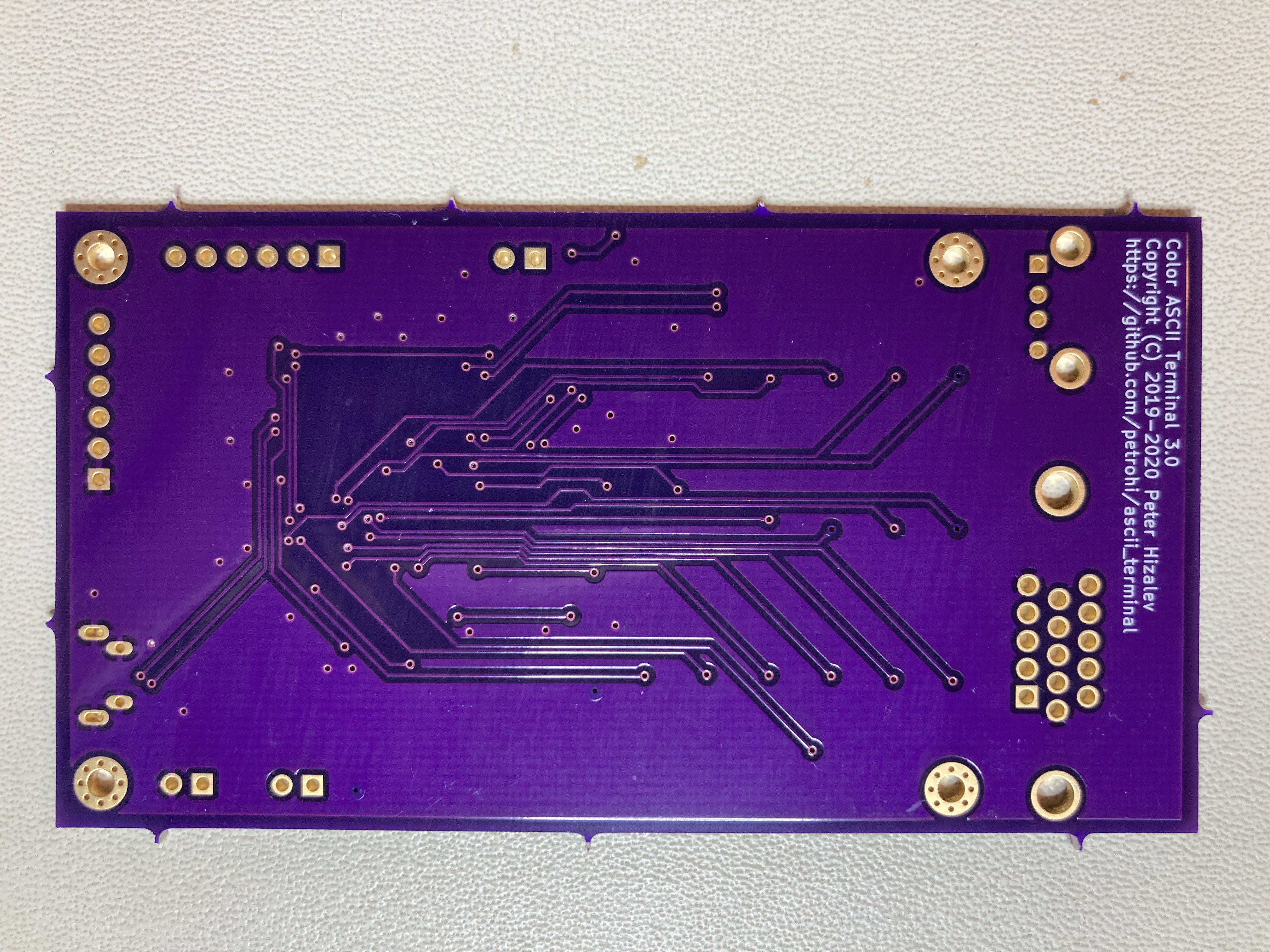
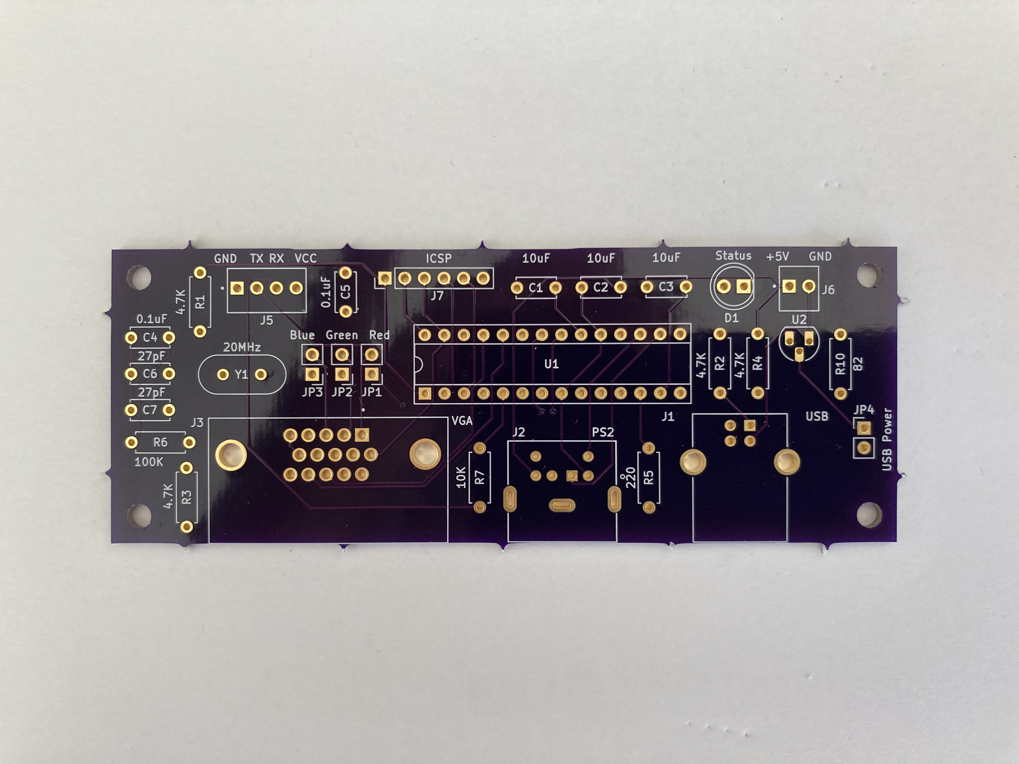
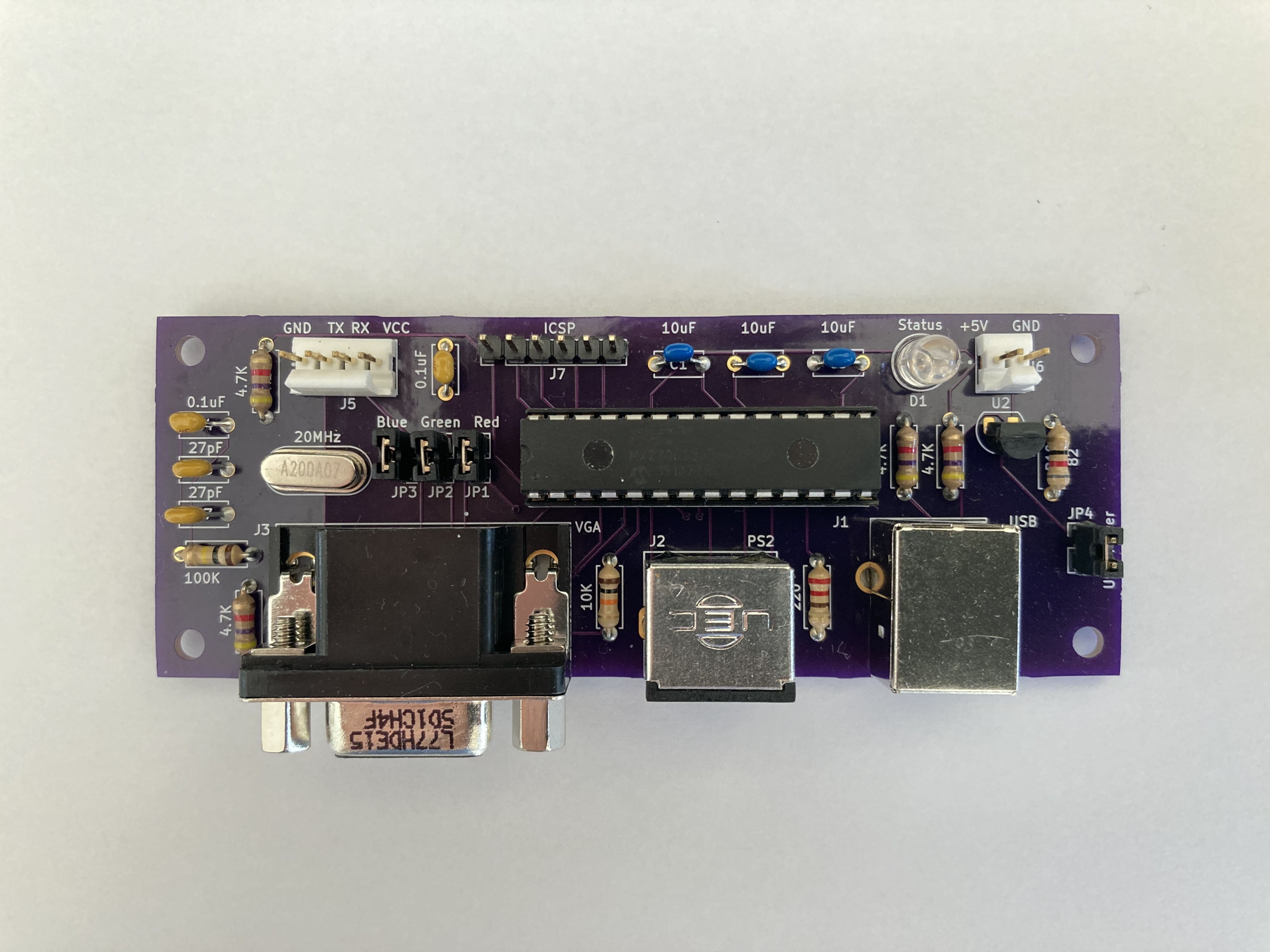
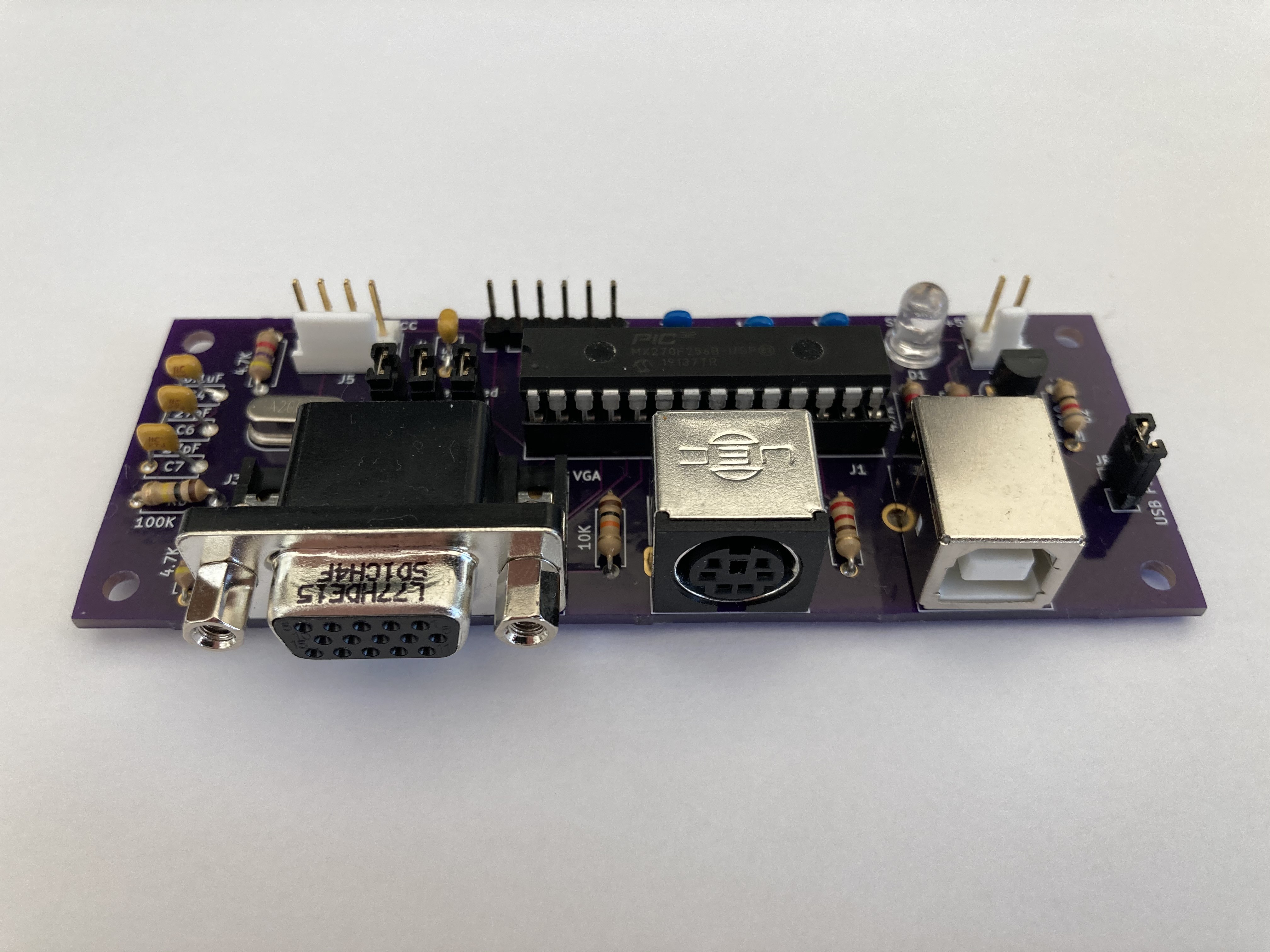
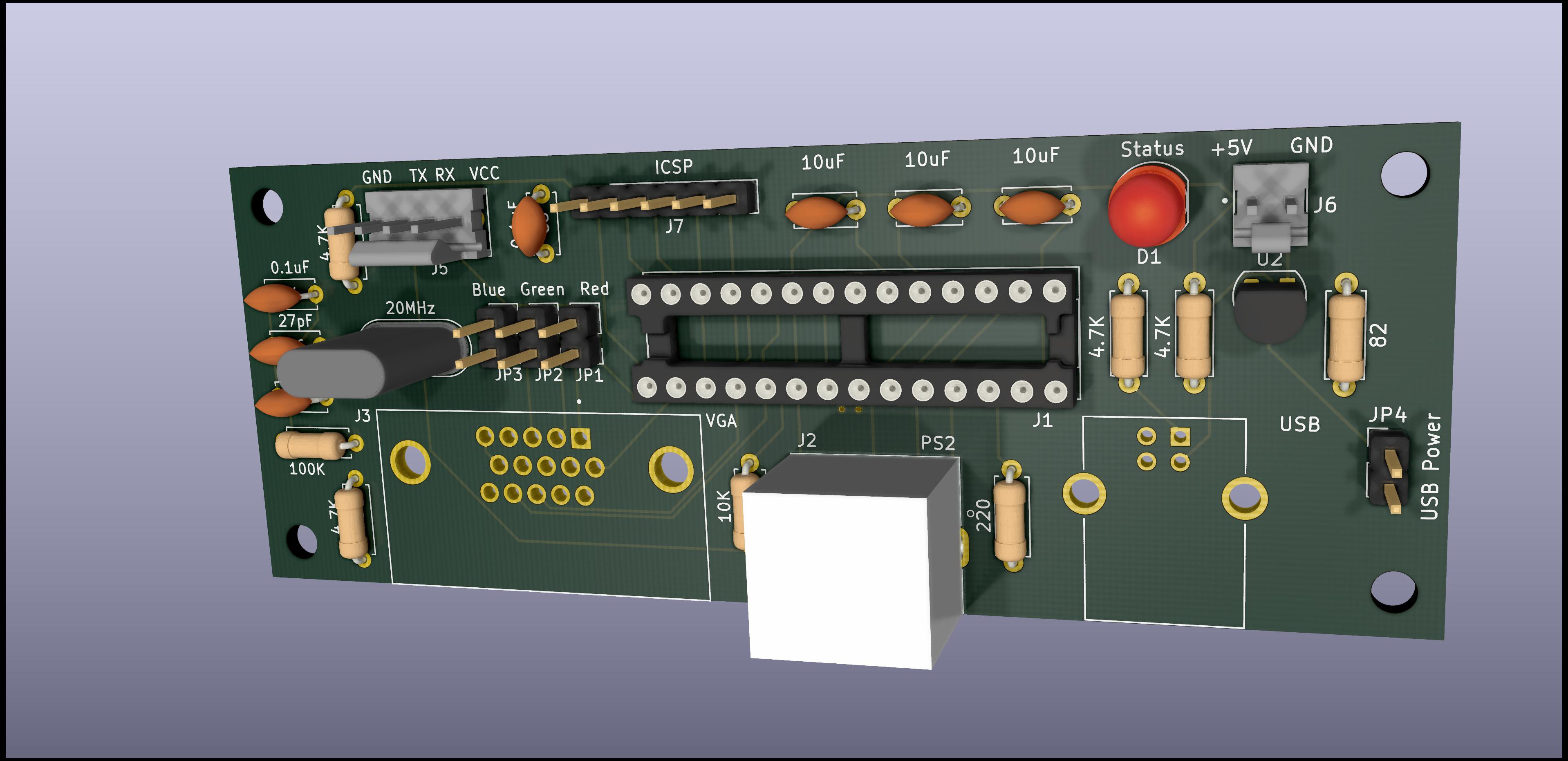
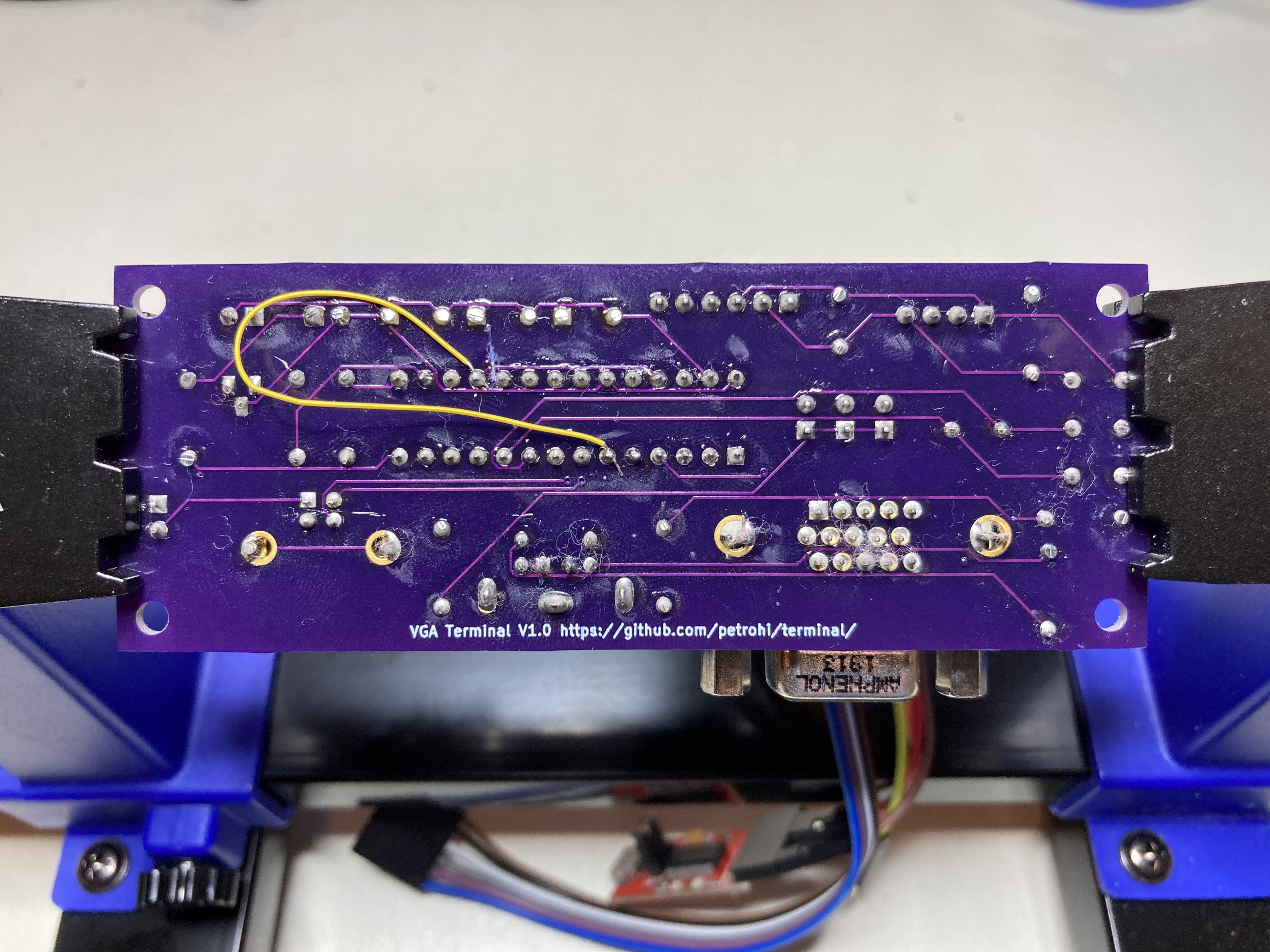
For PIC32-based terminal:

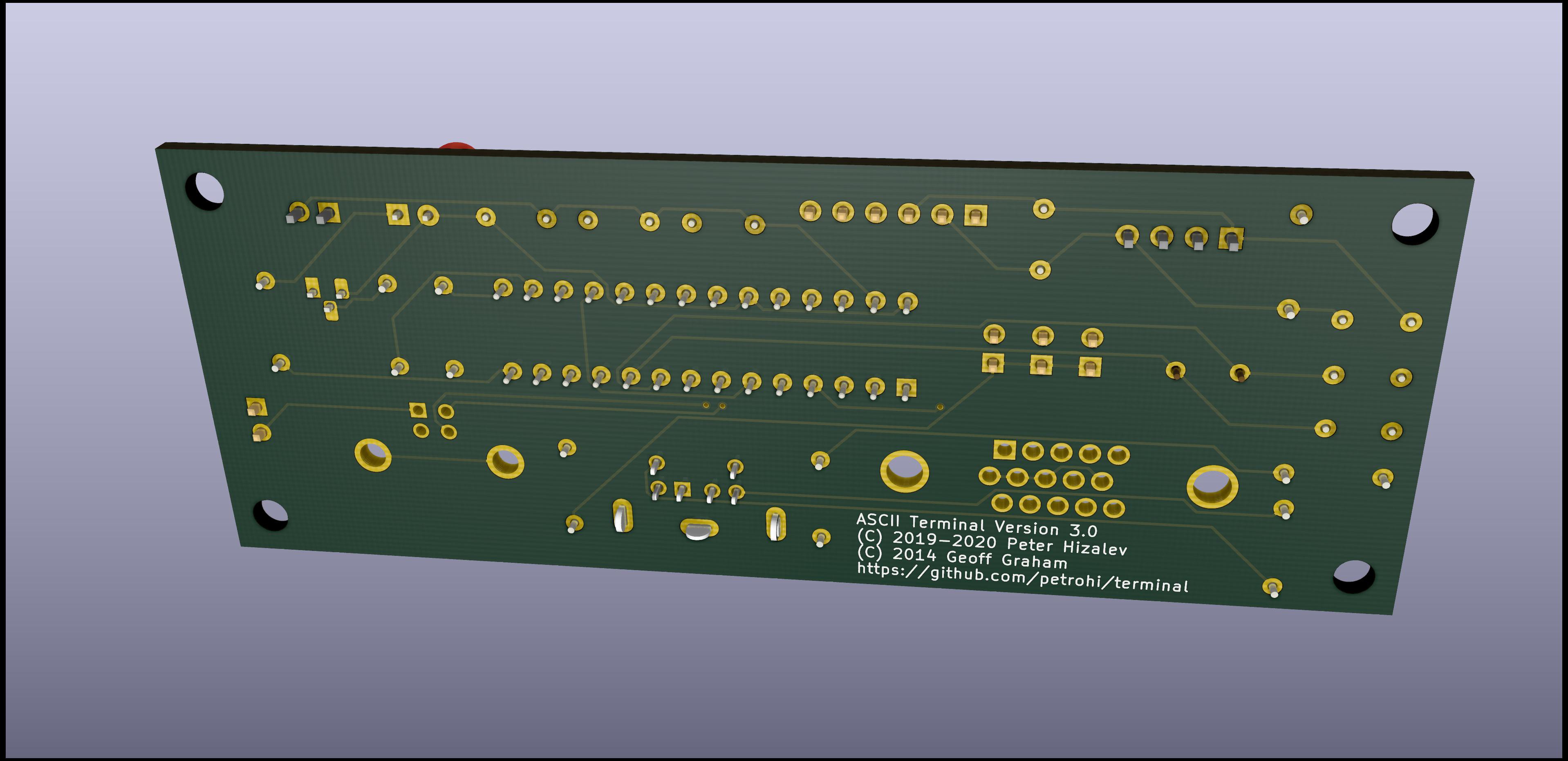
https://github.com/petrohi/terminal

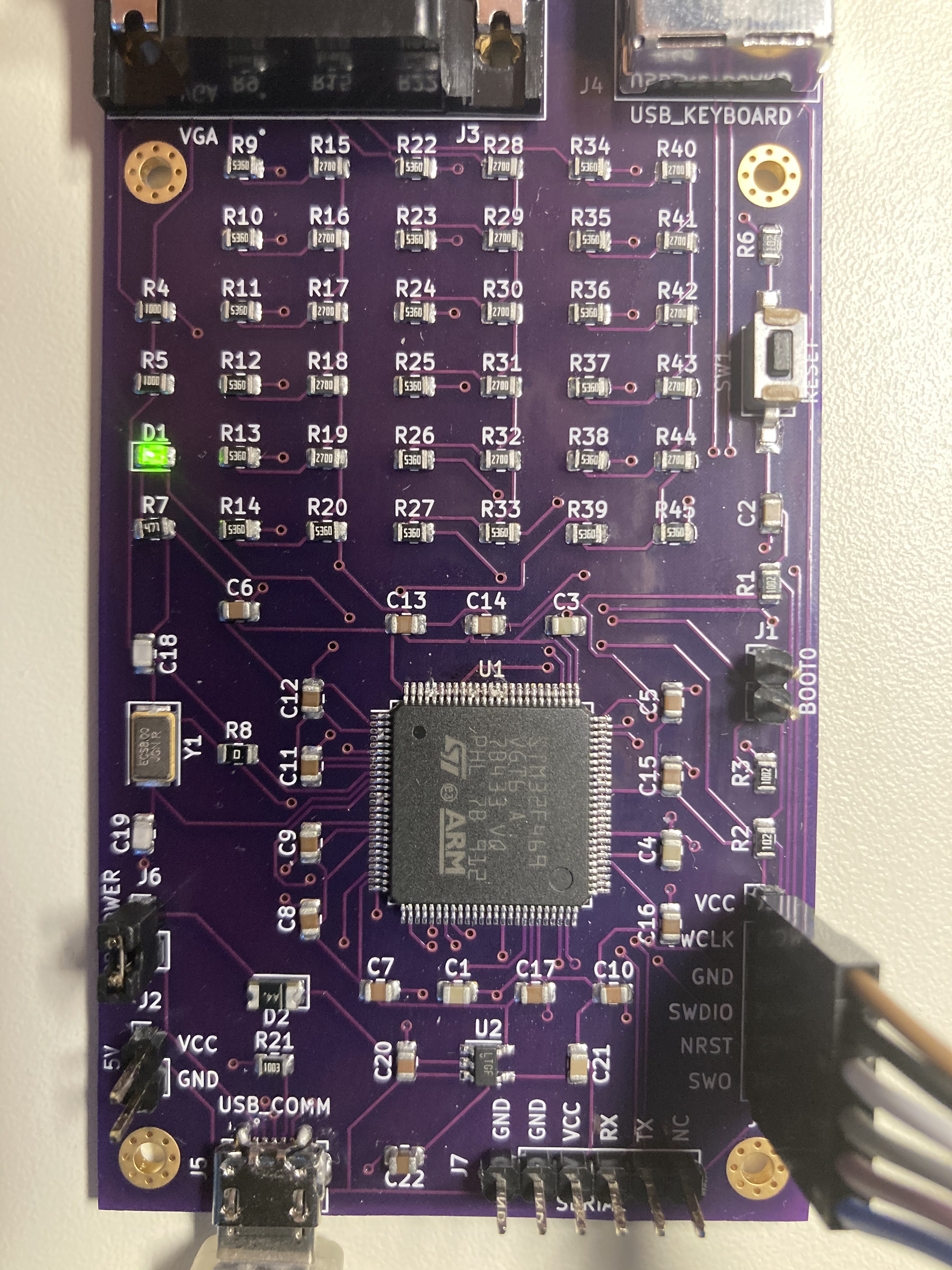
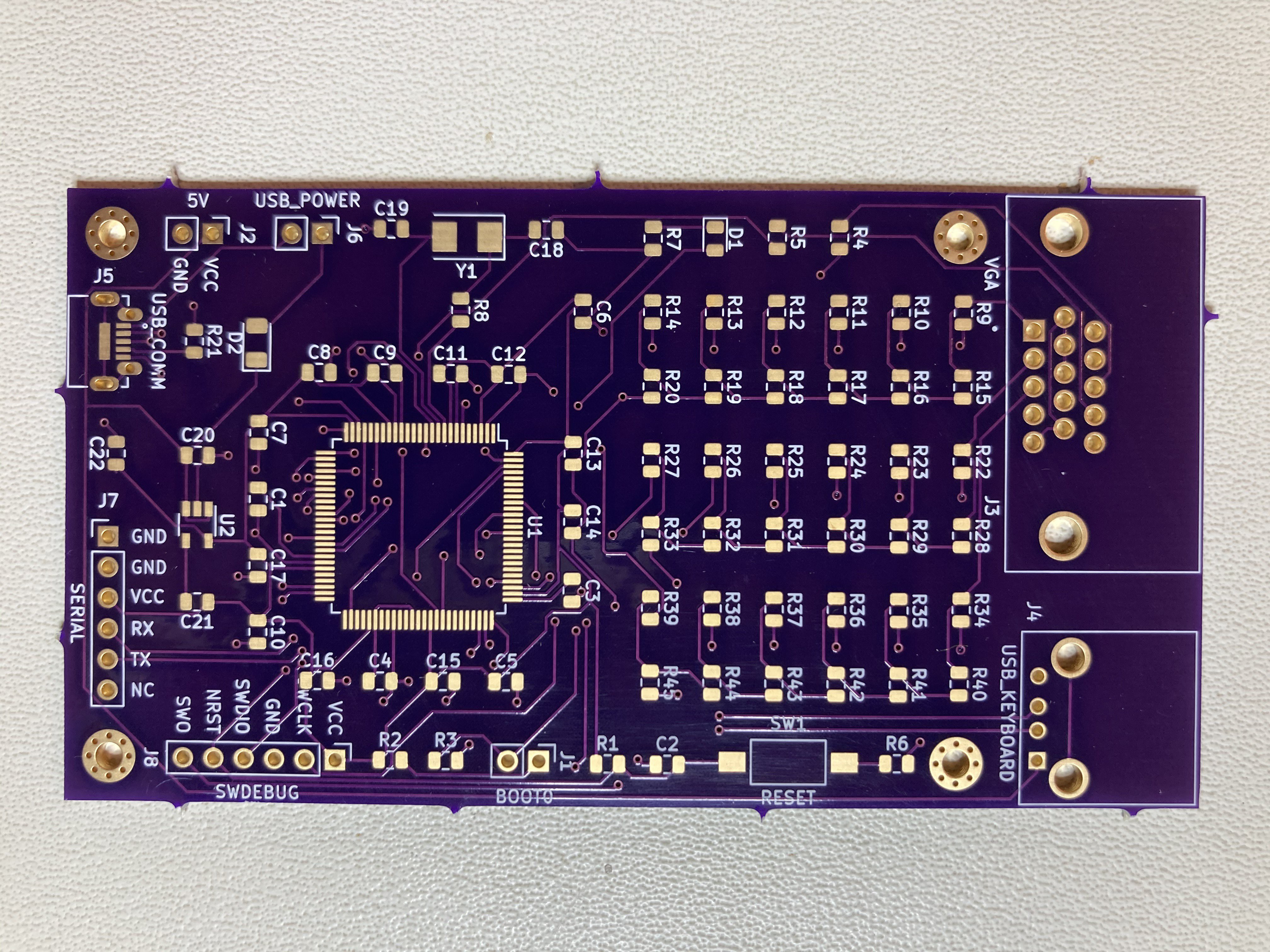
For STM32-based terminal:


https://github.com/petrohi/ascii_terminal

https://github.com/petrohi/ascii_terminal_kicad

  Are you sure? yes | no

morphriz wrote 03/25/2022 at 20:58 point

Do you have any files shared somewhere? Pcb etc.

  Are you sure? yes | no

Similar Projects

Does this project spark your interest?

Become a member to follow this project and never miss any updates