 Peter Hizalev
When Geoff's PIC32-based board got full VGA resolution overhaul there was a rather important consequence. The frame buffer became larger than the original and with that I had to reduce UART receive buffer. The latter change caused buffer overflows to happen much more often at high serial link speeds--in turn--resulting in missing text on the screen and frustrated users. What was even more upsetting, not all of the frame buffer memory was used to show useful pixels! Let me explain.
The VGA video signal has three main components: vertical sync, horizontal sync and the RGB pixel levels. The edge of vertical sync signals the beginning of the entire frame, which then consists of some number of lines. In turn, the edge of horizontal sync signals the beginning of the individual line. The RGB pixel levels continuously change for every pixel at a standard pixel clock.
For 640x480 VGA the typical pixel clock is 25MHz (25.175MHz to be precise) and there is a total of 525 lines per frame and 800 pixels per line. You would ask, why these numbers don't match 640x480? The answer is that the legacy CRT monitors needed time for the ray to transfer from the end of the line and from the end of the frame to beginning of the next one. During this transfer time the RGB level pixels could not be properly projected. Somehow the sync pulse time was not enough to accommodate the ray transfer! Therefore the standard introduced additional "quiet" time right before the sync pulse and right after. They called it front and back porches. The following picture from the STM32 reference manual that does a great job describing the timings:
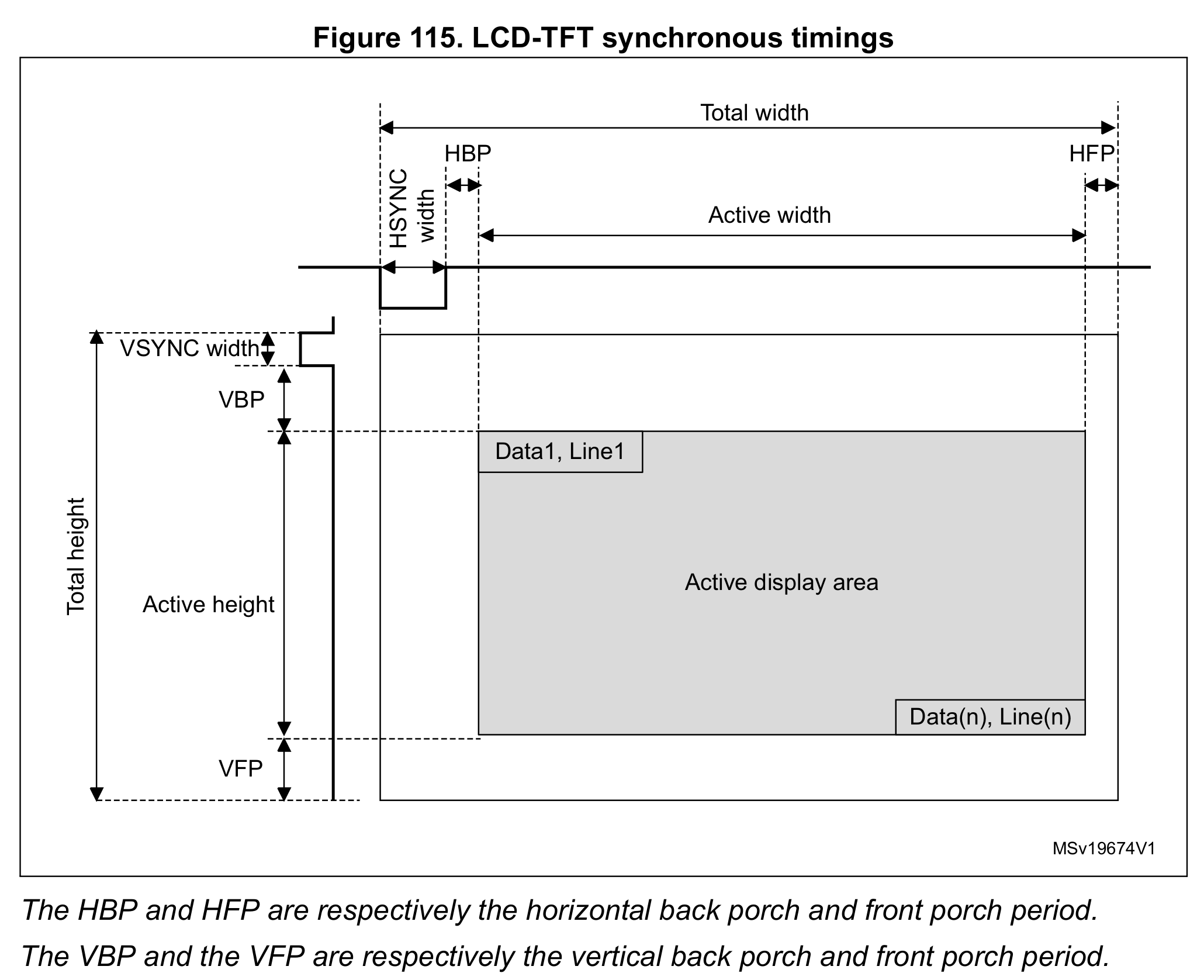
(Fun fact: if you tune you monitor image size and position you can actually "see" into these porches, so you can hack you monitor to show more pixels!)
Geoff's design cleverly uses SPI peripheral to push monochrome pixels at 25MHz. For every line there is a "line" timer interrupt at the edge of the horizontal sync. The interrupt continuously increments the line number and wraps it at the standard 525. Depending which line we are on, the interrupt might set or reset vertical sync output pin or take time to arm the DMA channel with the pointer of the next line of pixels in the frame buffer. To generate the horizontal sync pulse this design uses output compare (OC) pin that is triggered by the same line timer. Configuring OC3 is just the following one-liner: trigger the pulse from TIMER3 on count 0 and clear it on count VIDEO_H_SYNC_T.
OpenOC3(OC_ON | OC_TIMER3_SRC | OC_CONTINUE_PULSE, 0, VIDEO_H_SYNC_T);
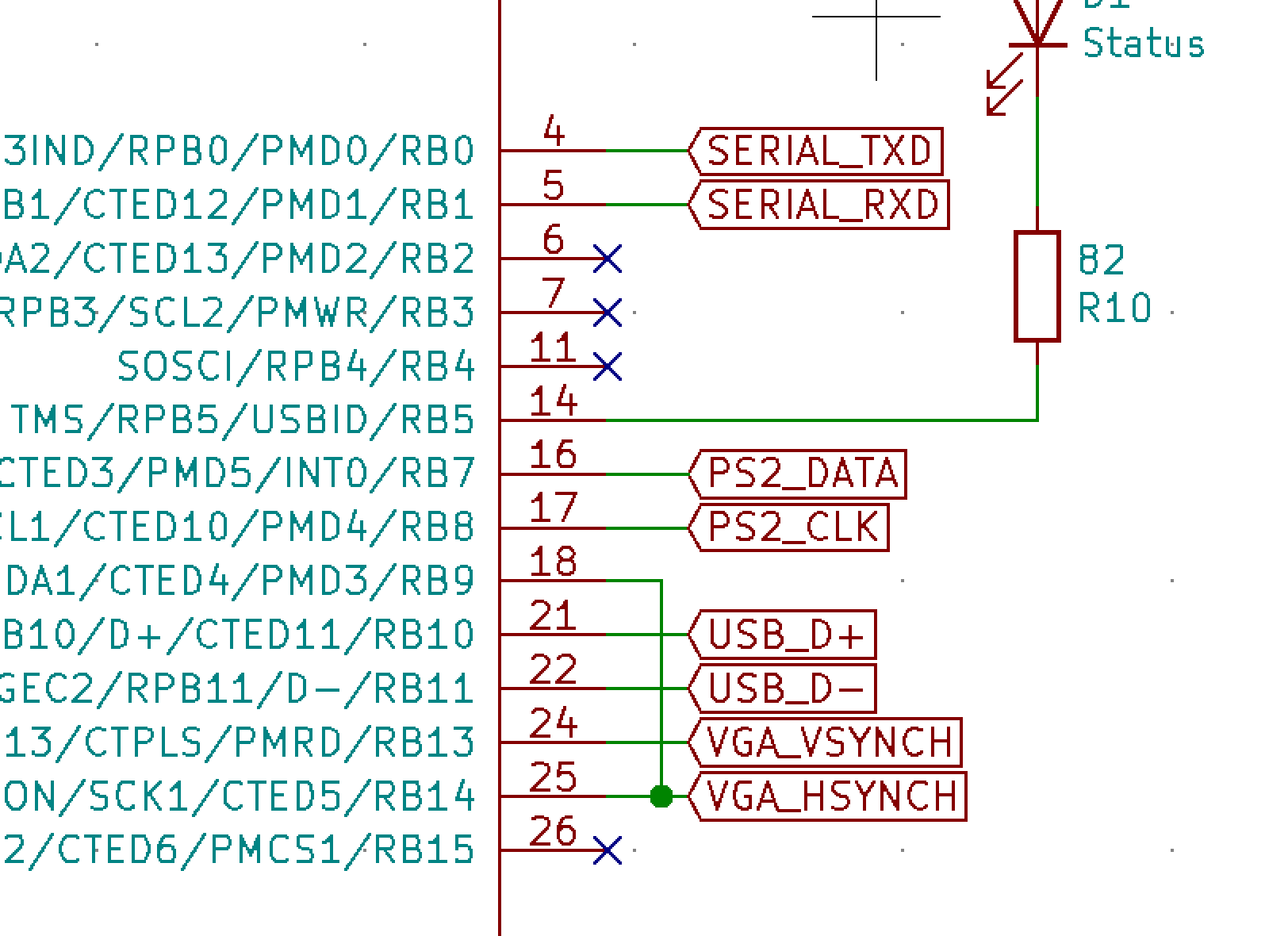
When the DMA is armed with the next line of pixels, we don't want the SPI to start transferring immediately because software execution time may vary. Instead, we want it to start at a very precise moment to make sure all lines are nicely aligned. Geoff's terminal--again very cleverly--uses the horizontal sync to do this! As soon as sync pulse is over the SPI starts transferring the line. Here is how this looks on the schematic. The RB14 is an output from the OC3 that generates horizontal sync pulse and it is connected to the RB9, which is an input to SPI framing:
And there lies the problem.
When the transfer starts right after the sync pulse we have to transfer the back porch pixels before starting the active pixels. For 640x480 VGA the horizontal back porch is 48 pixels. This means that the frame buffer must have every line front-padded with 6 bytes of zeroes. For 480 lines this is 2880 bytes of wasted space! And 2K could certainly make a difference when added to the UART receive buffer. How do we fix this?
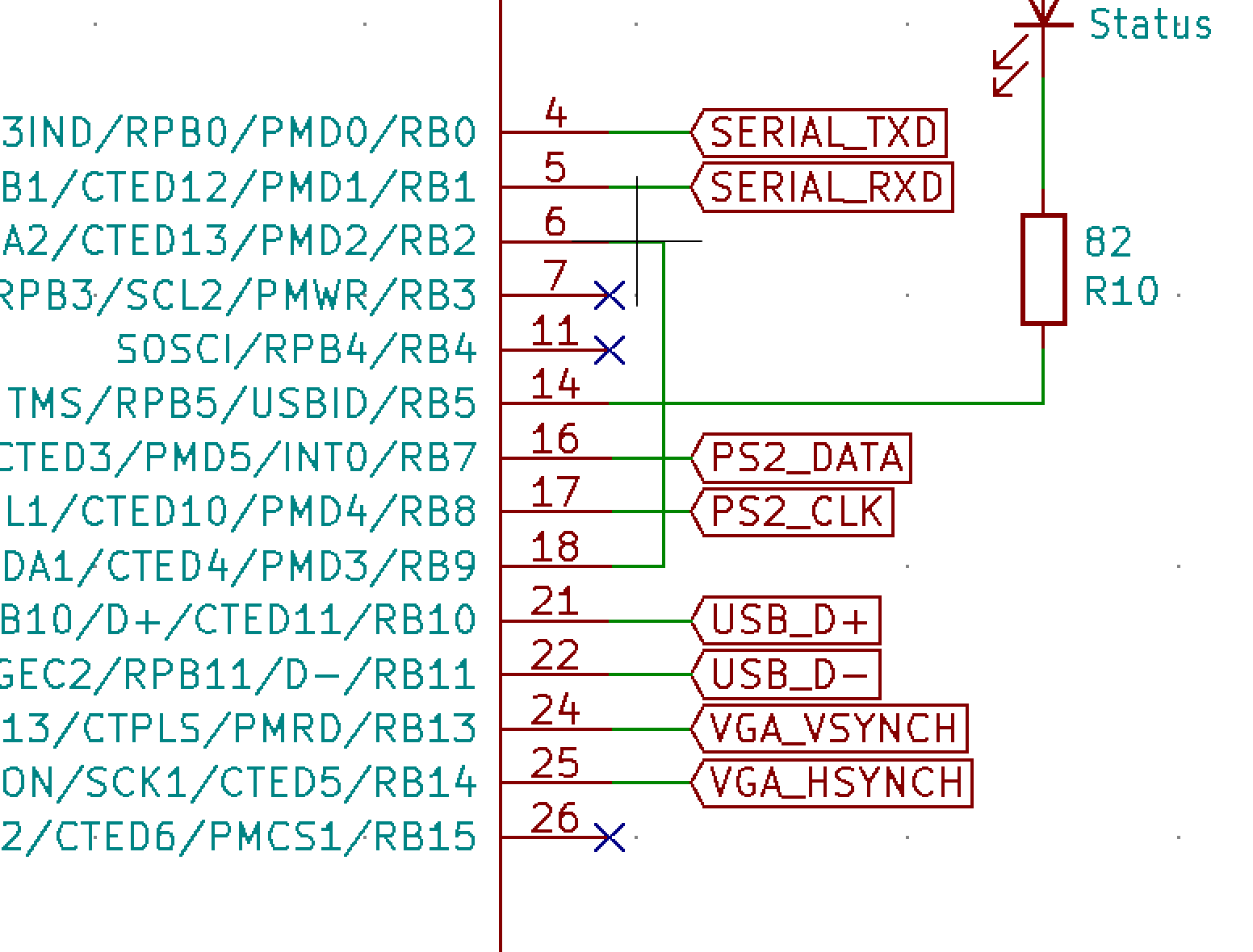
Why not have an alternative framing pulse that would let SPI transfer only during the active pixel time? In other words, we want the SPI to be quiet during both porches and the sync pulse. Conveniently, there is the OC4 peripheral connected to the RB2. Let's change the schematic as follows:
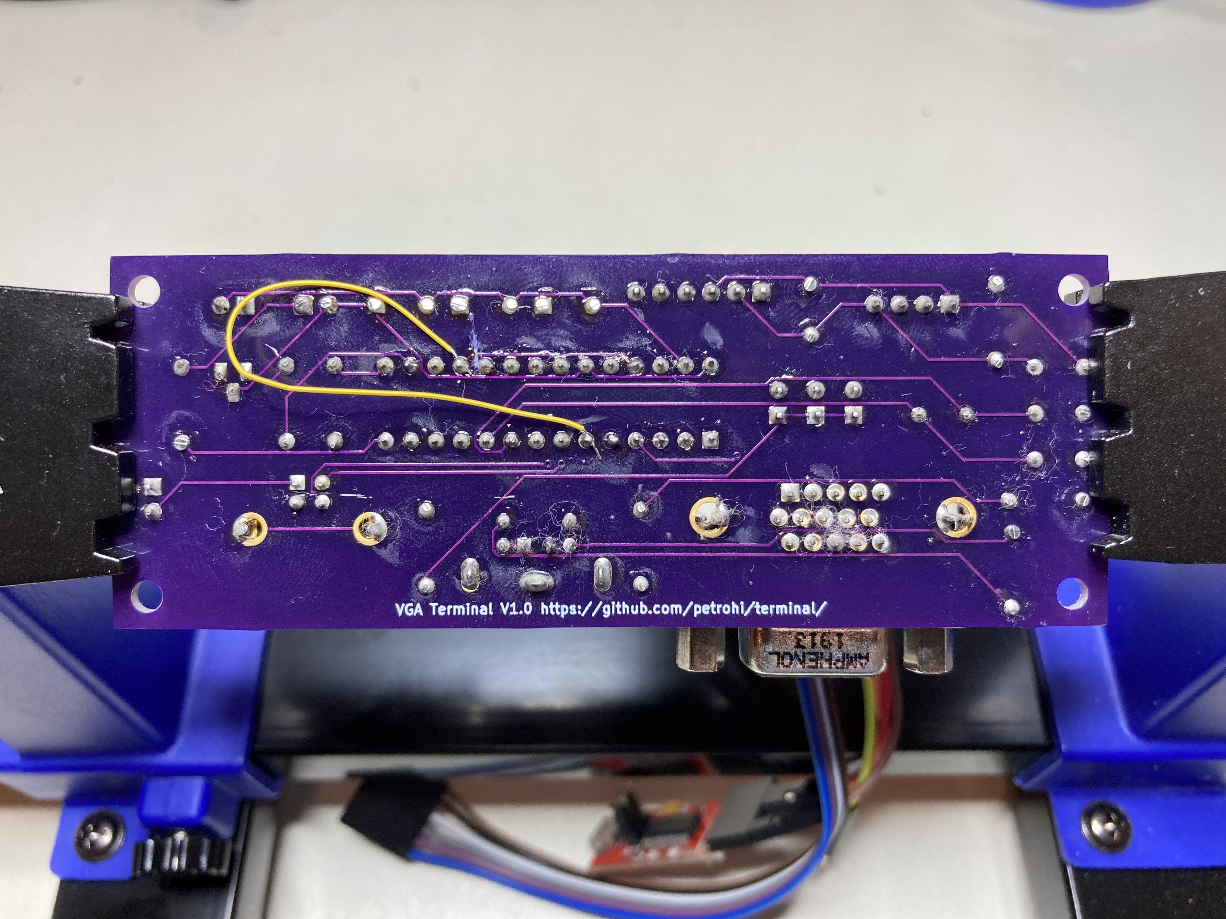
And hit the workbench to hack my board with a razor knife and soldering iron:
Now that hardware is ready lets modify the firmware. For this we need to configure both of our OCs to work in sync!
  OpenOC3(OC_ON | OC_TIMER3_SRC | OC_CONTINUE_PULSE, VGA_H_FRONT_PORCH_T,
          VGA_H_FRONT_PORCH_T + VGA_H_SYNC_T);
  OpenOC4(OC_ON | OC_TIMER3_SRC | OC_CONTINUE_PULSE, 0,
          VGA_H_FRONT_PORCH_T + VGA_H_SYNC_T + VGA_H_BACK_PORCH_T);
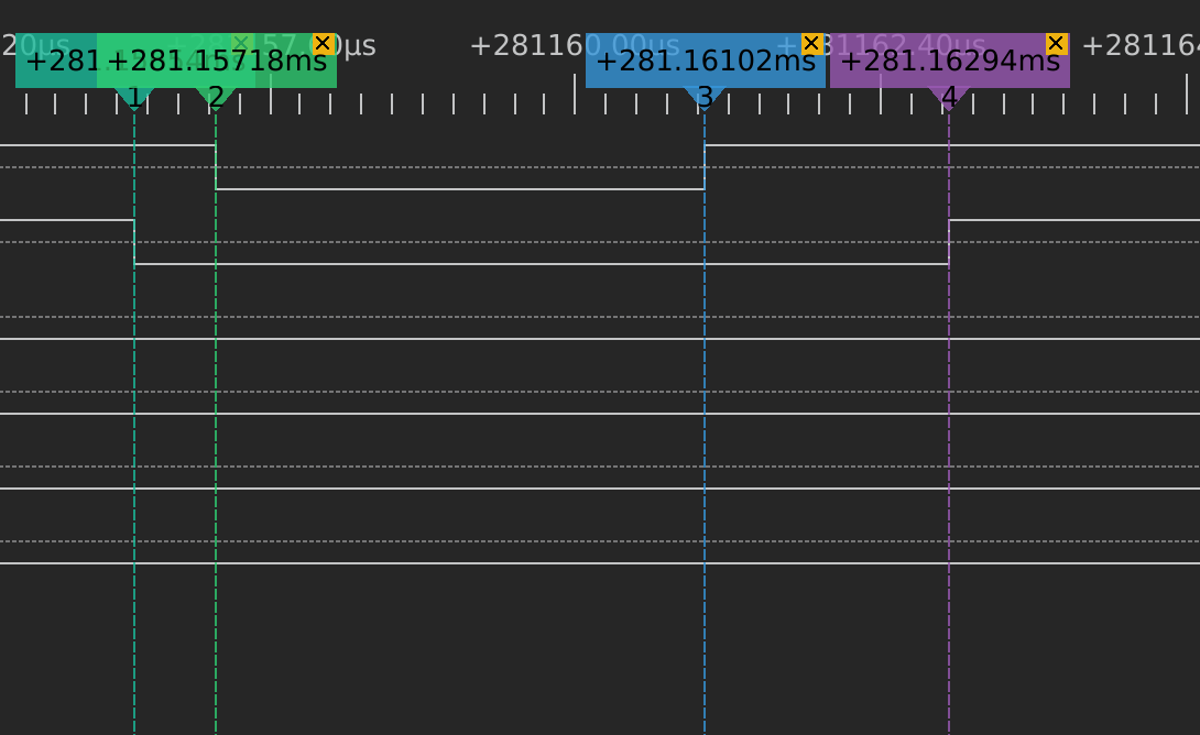
The horizontal sync (OC3) now triggers after counting to the front porch and clears after counting further to horizontal sync. The SPI framing (OC4) triggers at count 0 and clears when both porches and sync are counted. This is how this looks in the logic analyzer. The first line is OC3--the sync pulse and the second is OC4--the framing pulse.
With this change the SPI is sending precisely 640 pixels per line! This allows us to do another nice optimization--arming the DMA only once per frame and saving precious time spent in the interrupt handler.
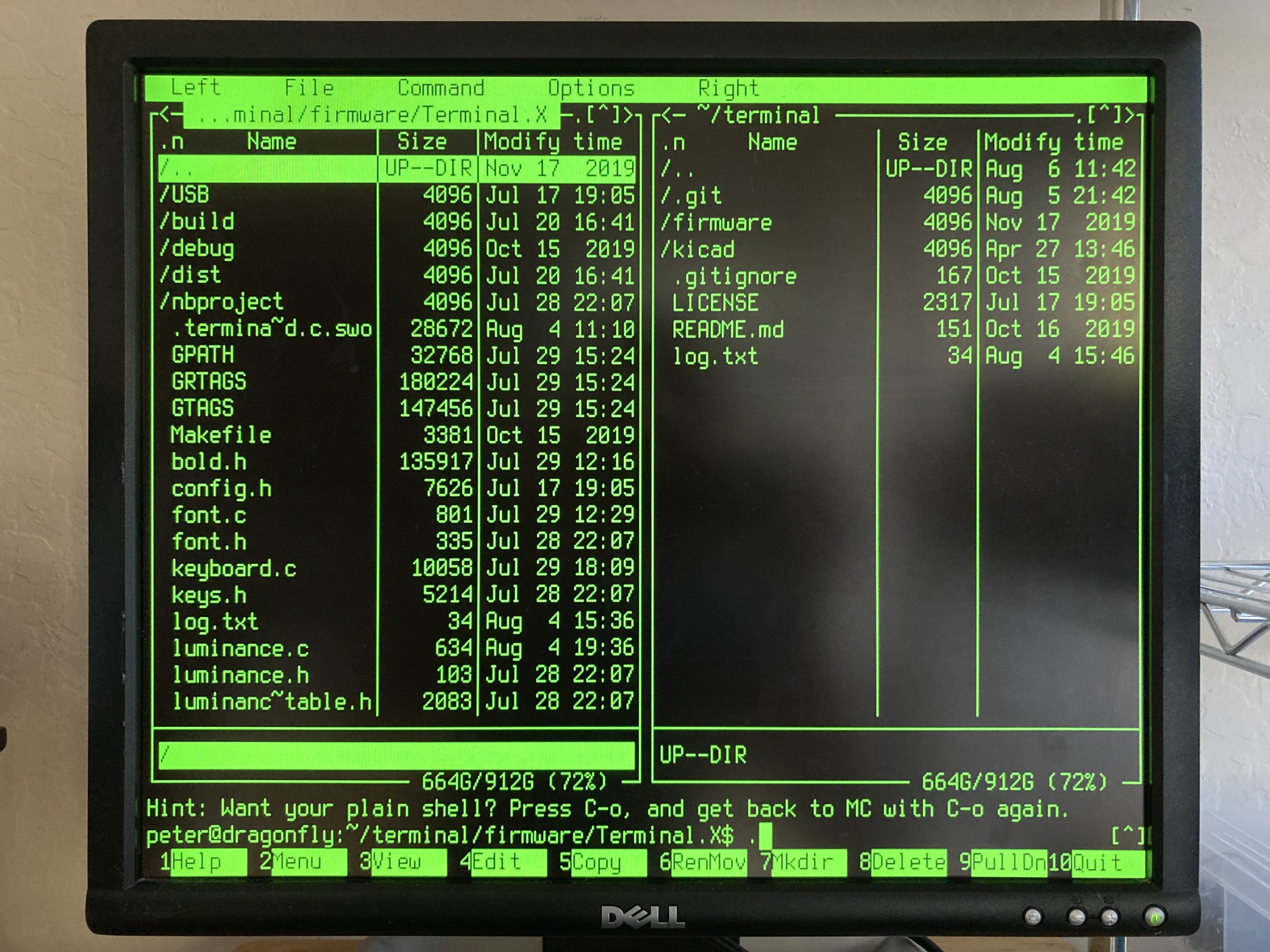
With UART receive buffer extended to 4K the terminal works nicely with Midnight Commander at 115200 Baud!
Discussions
Become a Hackaday.io Member
Create an account to leave a comment. Already have an account? Log In.