 engineerkid1
A rectifier circuit is used for converting Alternating Current (AC) to Direct current. Many rectifier circuit configurations are available including half wave rectifier, full wave rectifier, bridge wave rectifier, single phase, three phase, and controlled rectifier, each configuration has its own pros and cons. Bridge rectifier configuration is the most popular configuration due to the advantages including high efficiency, higher output power, low ripple factor and exception of center tap transformer.
D25XB60 is a silicon bridge rectifier integrated circuit. It is a single phase rectifier that handles the maximum peak reverse voltage of 600 V.
Features of D25XB60
- High current capability
- High surge current capability
- High reliability
- Low reverse current
- Low forward voltage drop
- Ideal for printed circuit board
- Very good heat dissipation
Replacement Part
GBJ 2506, GBJ 2508
Pictorial View
Pictorial view of the D25XB60 is shown below, it is a four terminal device that is available in UL94V-O package

Pin Description
Pin diagram and pin description of D25XB60 is given below

Pin Number | Pin Name | Description |
1 | + | DC output positive terminal |
2 | ~ | AC input |
3 | ~ | AC input |
4 | - | DC output negative terminal |
IC Electrical Characteristics/ Specifications
Some Electrical characteristic of the D25XB60 are given below
Parameter | Description | Value |
VRRM | Maximum Recurrent Peak Reverse Voltage | 600 V |
VRMS | Maximum RMS Voltage | 420 V |
VDC | Maximum DC Blocking Voltage | 600 V |
IF(AV) | Maximum Average Forward Current | 25 A |
IFSM | Peak Forward Surge Current | 350 A |
VF | Maximum Forward Voltage per Diode | 1.05 V |
IR | Maximum DC Reverse Current | 10 µA |
TJ | Operating Junction Temperature Range | -40 to 150 C |
T`` | TSTG - 40 to + 150 ° | -40 to 150 C |
Working Principle
Many electronic applications require regulated DC and the most reliable way to provide DC is via rectification of the AC. Bridge rectifier configuration is the widely used to provide DC due to certain advantage that are mentioned above.
Bridge rectifier circuit requires four diodes, which are generally represented in shape of diamond/ bridge on the circuit diagrams hence called bridge rectifier. AC signal consists of positive half cycle and negative half cycle, during the positive half cycle two of the four diode of bridge configuration conducts and for the negative half cycle other two diode of the bridge rectifier conducts. By the virtue of this configuration current is allowed to pass through the circuit in only one direction and DC is produced. A bridge rectifier circuit can be formed using discrete electronic components however off the shelf integrated circuit like D25XB60 are also available
Applications
Utsource D25XB60can be used in the below applications
- Charging circuits
- Portable applications
- Adaptors
- Power supplies
Typical Application Circuit
a typical application circuit for the D25XB60 is shown in figure below, it is converting alternating current to the direct current

 Electroniclovers123
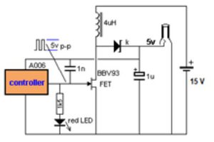
 kamalkedin123
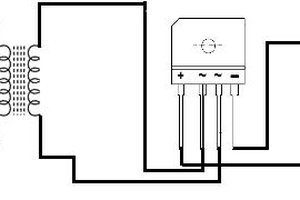
 256byteram