 kamalkedin123
Information in differential line drivers is transmitted using two opposite signals. They send the same electrical signal as two unlike signals, each on a conductor of its own. The conductors can either be a track on a circuit board or wires that are paired together.
HD29051is a differential line driver/ receiver with three state output design. Each device has two drivers/ receivers in a sixteen pin package
Features of HD29051FP
- Built in current limit for short circuit
- Power up/ down protection
- High output current
- Input hysteresis
- In phase input voltage
Replacement Part
SN7534050, SN7534051
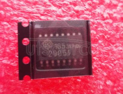
Pictorial View
Pictorial view of UTSource HD29051FPis shown below, it is available in sixteen pin FP-16DA package
Pin Description
Pin description and pin diagram of HD29051FP is given below

Pin Number | Pin Name | Description |
1 | R1B | 1st Schmitt trigger inverting input |
2 | R1A | 1st Schmitt trigger non inverting input |
3 | R1Y | 1st Schmitt trigger output |
4 | D1 ENABLE | Data enable first channel |
5 | R2Y | Output of 2nd Schmitt trigger |
6 | R2A | 2nd Schmitt trigger non inverting input |
7 | R2B | 2nd Schmitt trigger inverting input |
8 | GND | Ground |
9 | D2A | Data input second channel |
10 | D2Y | Output Y |
11 | D2Z | Output Z |
12 | D2 ENABLE | Data enable second channel |
13 | D1Z | Output Z |
14 | D1Y | Output Y |
15 | D1A | Data input first channel |
16 | VCC | Power supply |
IC Electrical Characteristics/ Specifications
Some Electrical characteristic of HD29051FP are given below
Parameter | Description | Value |
VCC | Supply voltage | 7 V |
VIN | Input voltage A, B | ± 25 V |
VID | Differential input voltage | ± 25 V |
IO | Output current | 50 mA |
VIE | Enable input voltage | 5.5 V |
VIN | Input voltage | 5.5 V |
VO | Output applied voltage | -1 to 7 V |
TOPR | Operating temperature range | 0 to 70 V |
TSTG | Storage temperature | -65 to 150 C |
Working Principle
Differential signaling is a method for electrically transmitting data using two opposite signals. In this technique the same electrical signal is sent as a differential pair signal. the receiver circuit responds to the difference between two electrical signals. This technique affects the performance of the circuit against the electromagnetic noise.
Applications
Differential line driver/ receiver can be used in following applications
- Balanced audio circuits
- Digital signaling
Noise Cancellation using Differential Receiver in Digital Circuits
A diagram of a representative circuit for differential receivers is shown. Not here due to differential input, input pulse is received with high amplitude and noise is cancelled due to differential effect.

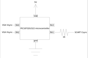
Signal Transmission
Differential line driver/ receiver is used in signal transmission is shown in the circuit below.

 SCART VADER
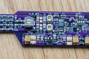
 Bud Bennett
 Electroniclovers123
How is this a project? More a datasheet and application notes. Inappropriate.