 svofski
This was a big update which hackaday bloody engine screwed up and failed to save. I understand it's a rebel site and it can't be all rosy-pop bubblegum happy, and I appreciate the service anyway, but nnnnggggggghhh!....
Anyway, implemented some bearable vertical 3:5 scaling so that the entire visible height of v06c screen area fits in 480 lines available on my LCD. Input data: TV-like picture, 312 lines. For VGA we do scan-double and hope that the TV/monitor somehow stuffs it up in a kind of PAL 752x568 mode. Here I don't have that, just a raw LCD glass so I need to scale it myself. Visible line count = 16 + 256 + 16 = 288. 288 * 5 / 3 = 480. This is how the numbers came to be.
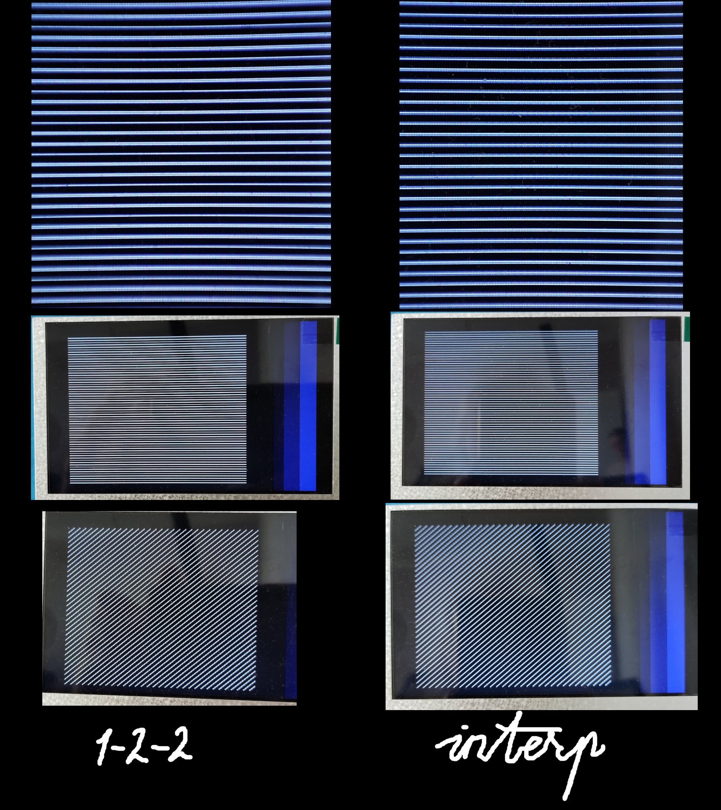
Left: simple 1-2-2 repeated lines, right - a slightly broken due to physical limitations linear interpolation. It's easy to tell that it exists using tests, but otherwise it's quite good. By the way, it's difficult to capture this difference on a phone camera, which I believe uses its own anti-moire filters that make everything look more or less okay. Real-life difference between the left and the right pictures is more obvious.
Some trick that I'm using: for every 3 source lines (TV-speed lines) I need to produce 5 LCD lines. So it's not a simple scan doubler. And I found that I can simply skip 6th line on the LCD. It works. But it breaks something in its glassy brain, so you need to feed it with more HSYNC pulses later. If you don't it will skip VSYNC and you'll be only getting even frames, and the liquid crystals will twist too far and there will be image retention artifacts.
My theory is that in proper scan mode, it twists/untwists them in opposite direction. If you somehow miss the frame, it continues to twist them in the same direction. Would be interesting to find out more about this. I had the same kind of artifact on ESP32S3, but there I had little control over the scanning process and I think it was always overtwisting. At least it was very prone to image retention.
Proper interpolation would require some real maths. I simplified things a little bit. When computing 5 vertical pixels, every pixel is a sum of 4 terms. So by altering which source pixels go in I can adjust their relative weight. I distributed 3 input pixels evenly, so e.g. 7+7+6 and that's it. The actual code looks like this:
pipmix4 ma1(clk24, rc_a[0], rc_a[0], rc_a[0], rc_a[0], bmix[0]);
pipmix4 ma2(clk24, rc_a[0], rc_a[0], rc_a[0], rc_a[1], bmix[1]);
pipmix4 ma3(clk24, rc_a[1], rc_a[1], rc_a[1], rc_a[1], bmix[2]);
pipmix4 ma4(clk24, rc_a[1], rc_a[1], rc_a[2], rc_a[2], bmix[3]);
pipmix4 ma5(clk24, rc_a[2], rc_a[2], rc_a[2], rc_a[2], bmix[4]);

...

// pipelined mix = a + b + c + d in 3 stages
// input components are bgr233, output mix is bgr555
// s1 = a + b
// s2 = s1 + c
// s3 = s2 + d + 1
module pipmix4(input clk, input [7:0] a, input [7:0] b, input [7:0] c, input [7:0] d, output [14:0] mix);

reg [4:0] rp [2:0];
reg [4:0] gp [2:0];
reg [4:0] bp [2:0];

reg [7:0] aq [1:0];
reg [7:0] bq [1:0];
reg [7:0] cq [1:0];
reg [7:0] dq [1:0];

always @(posedge clk)
begin
    aq[1] <= aq[0]; aq[0] <= a;
    bq[1] <= bq[0]; bq[0] <= b;
    cq[1] <= cq[0]; cq[0] <= c;
    dq[1] <= dq[0]; dq[0] <= d;


    rp[0] <= a[2:0] + b[2:0];               // stage 0
    rp[1] <= rp[0]  + cq[0][2:0];           // stage 1
    rp[2] <= rp[1]  + dq[1][2:0] + 1'b1;    // stage 2

    gp[0] <= a[5:3] + b[5:3];
    gp[1] <= gp[0]  + cq[0][5:3];
    gp[2] <= gp[1]  + dq[1][5:3] + 1'b1;

    bp[0] <= a[7:6] + b[7:6];
    bp[1] <= bp[0]  + cq[0][7:6];
    bp[2] <= bp[1]  + dq[1][7:6] + 1'b1;
end
Resolution:
Discussions
Become a Hackaday.io Member
Create an account to leave a comment. Already have an account? Log In.