 jaromir.sukuba
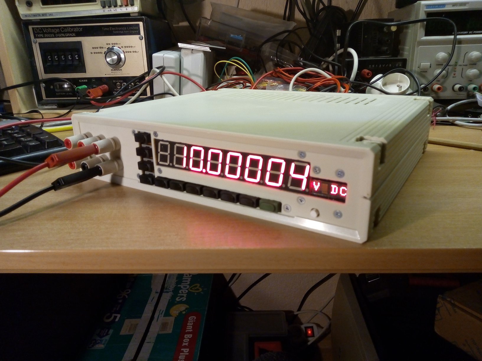
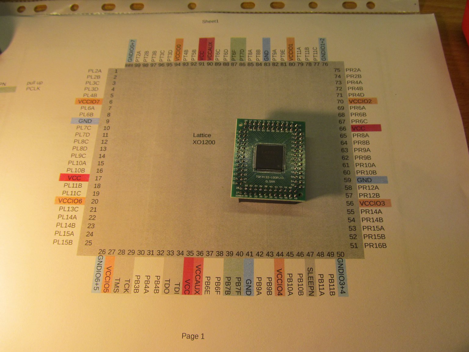
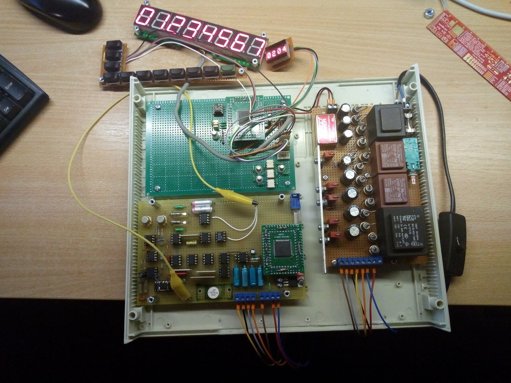
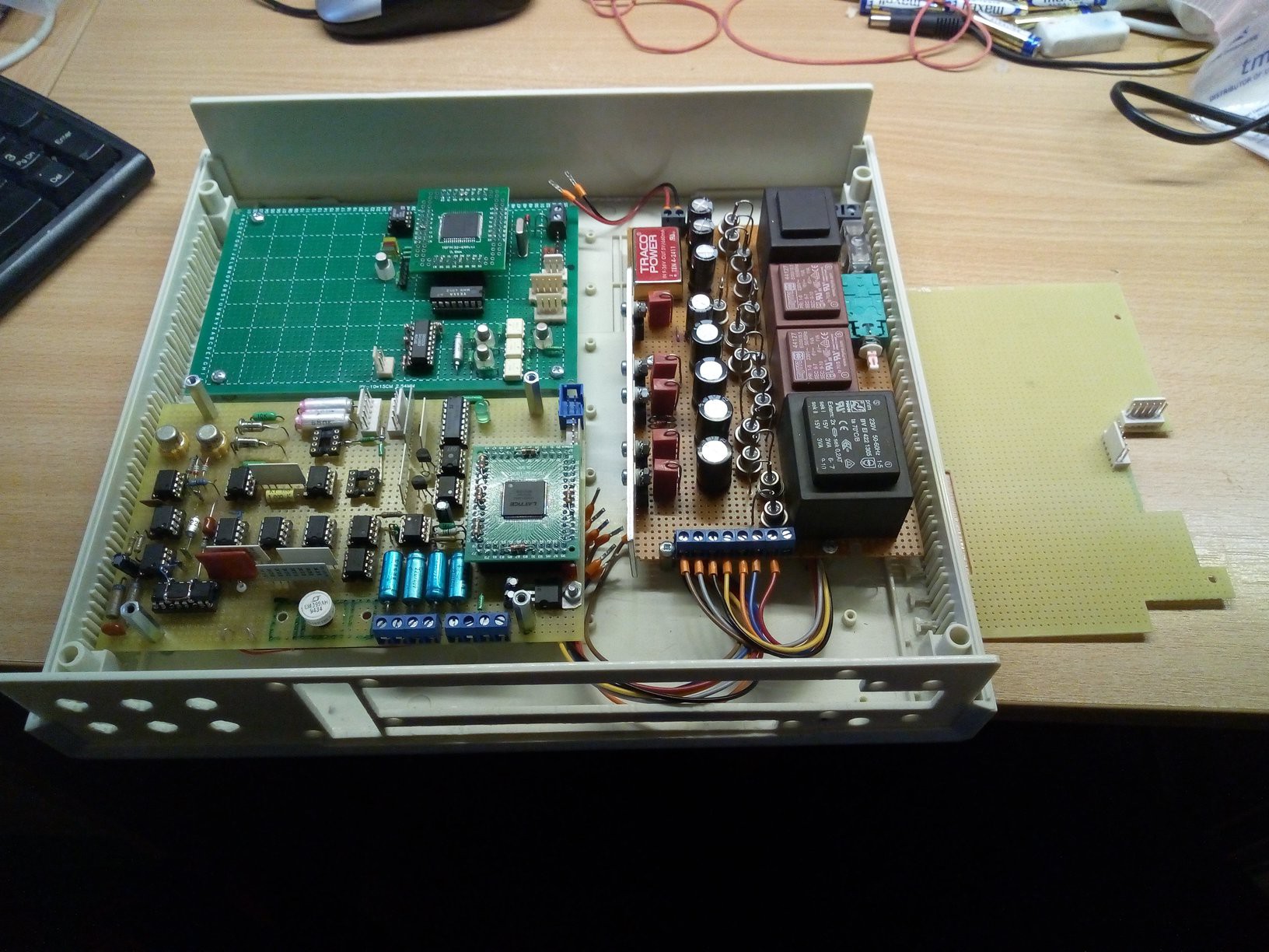
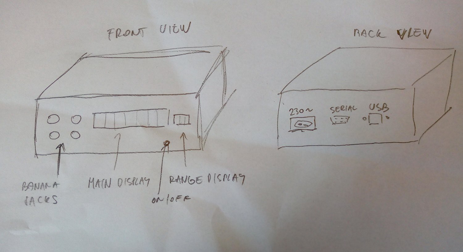
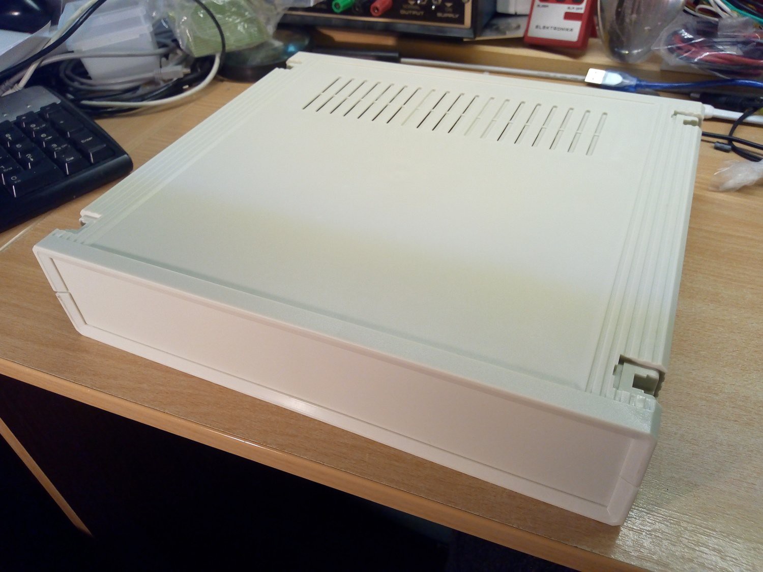
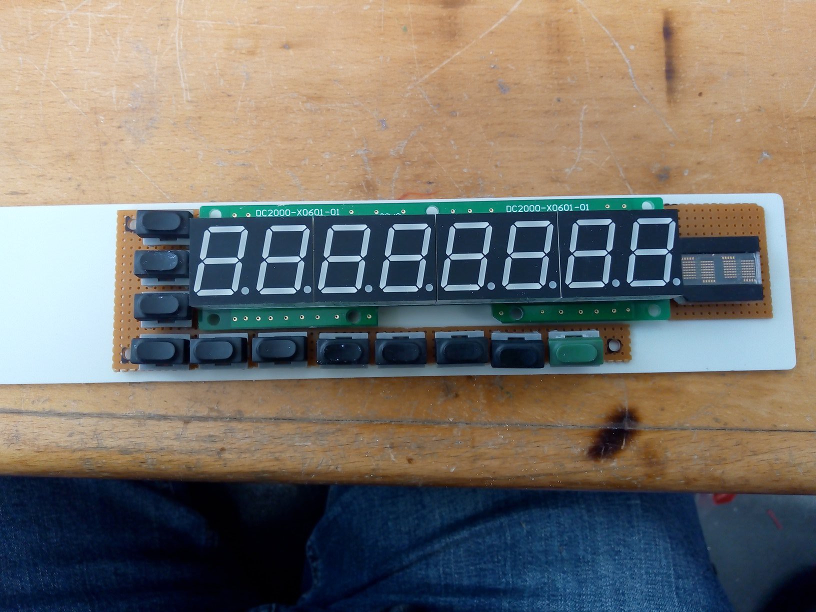
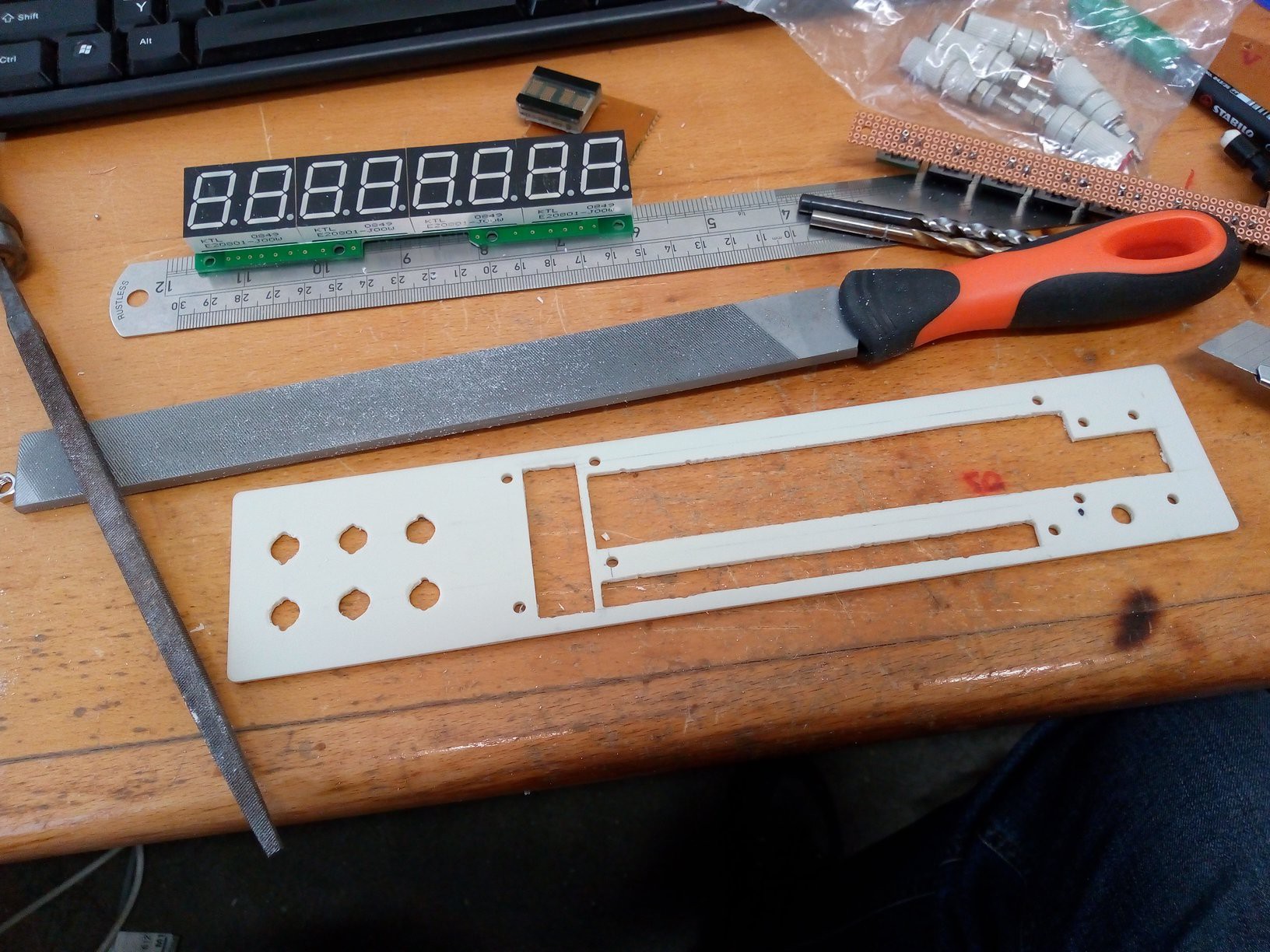
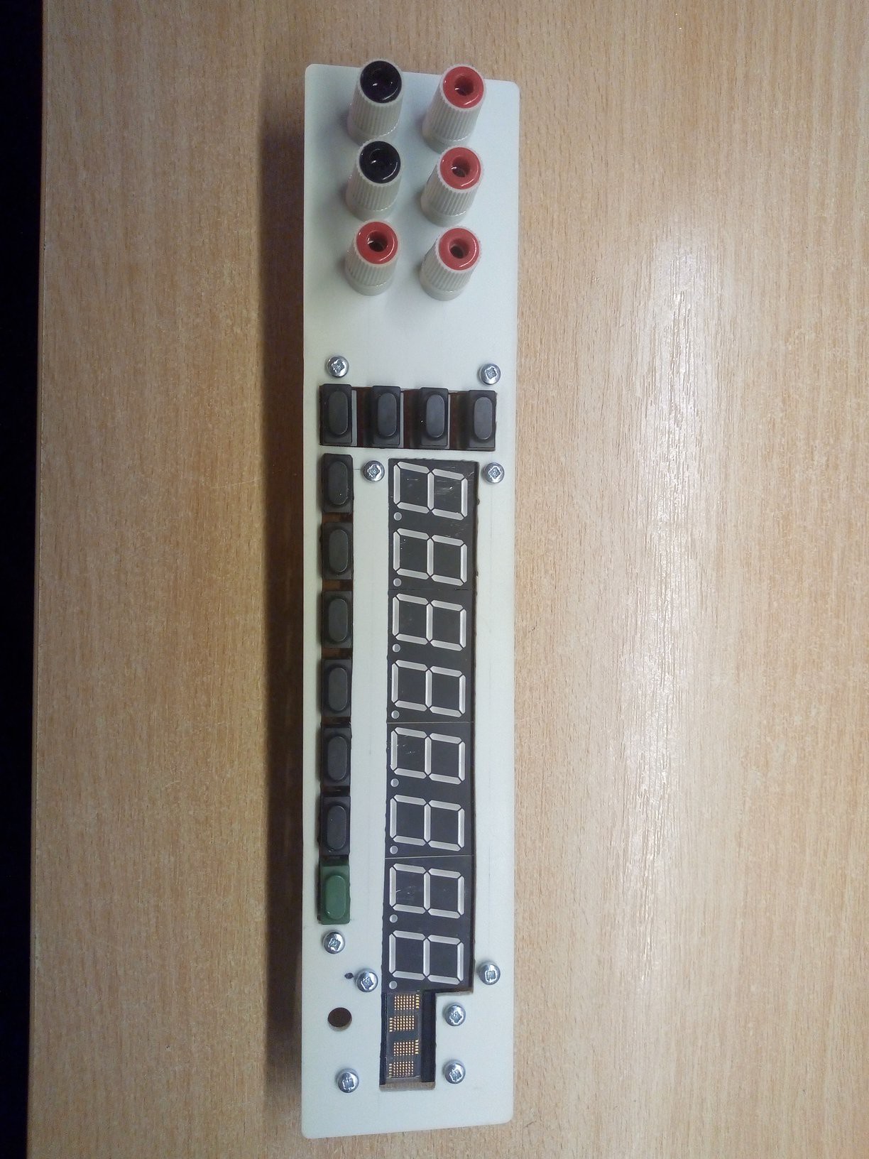
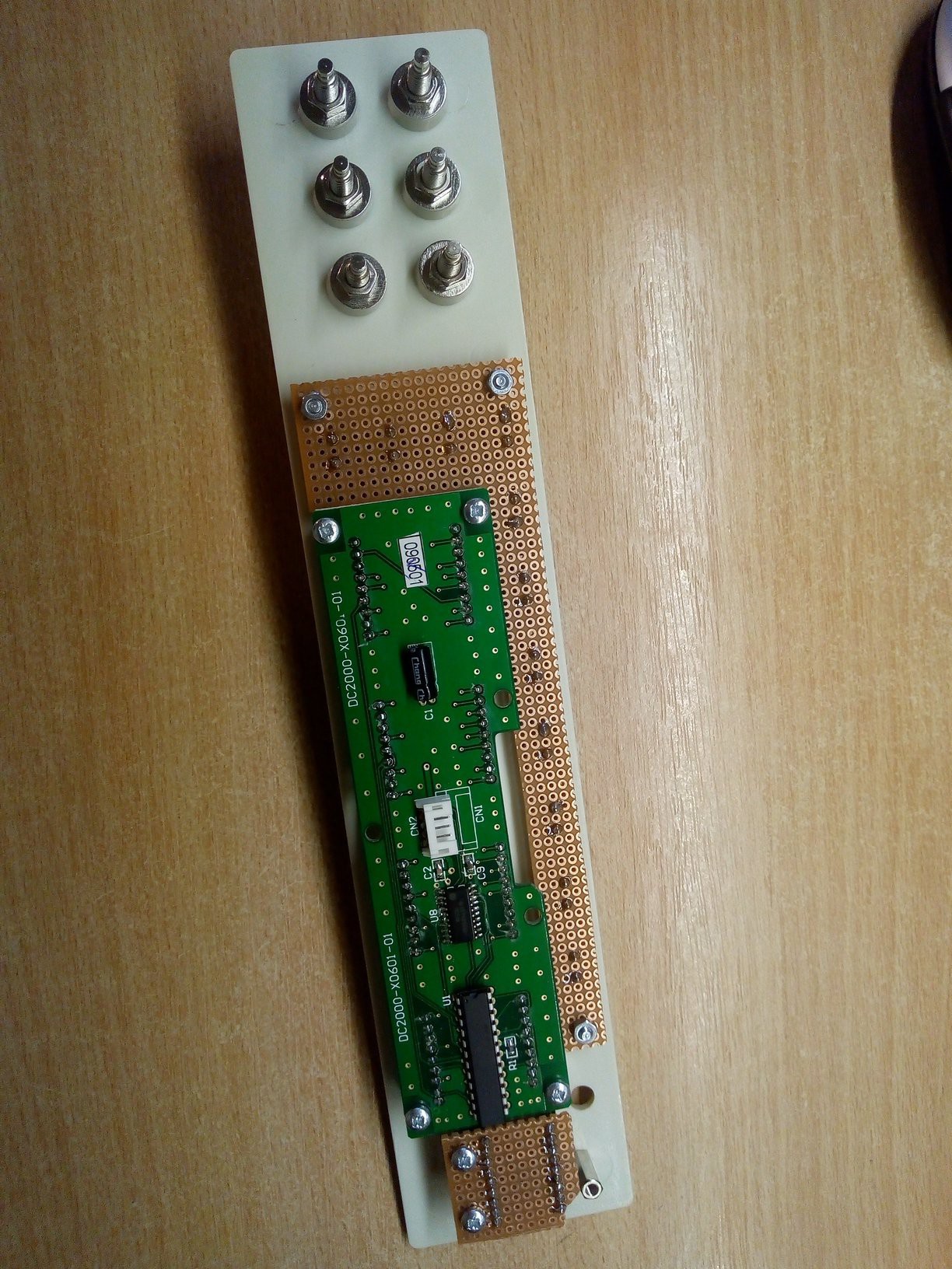
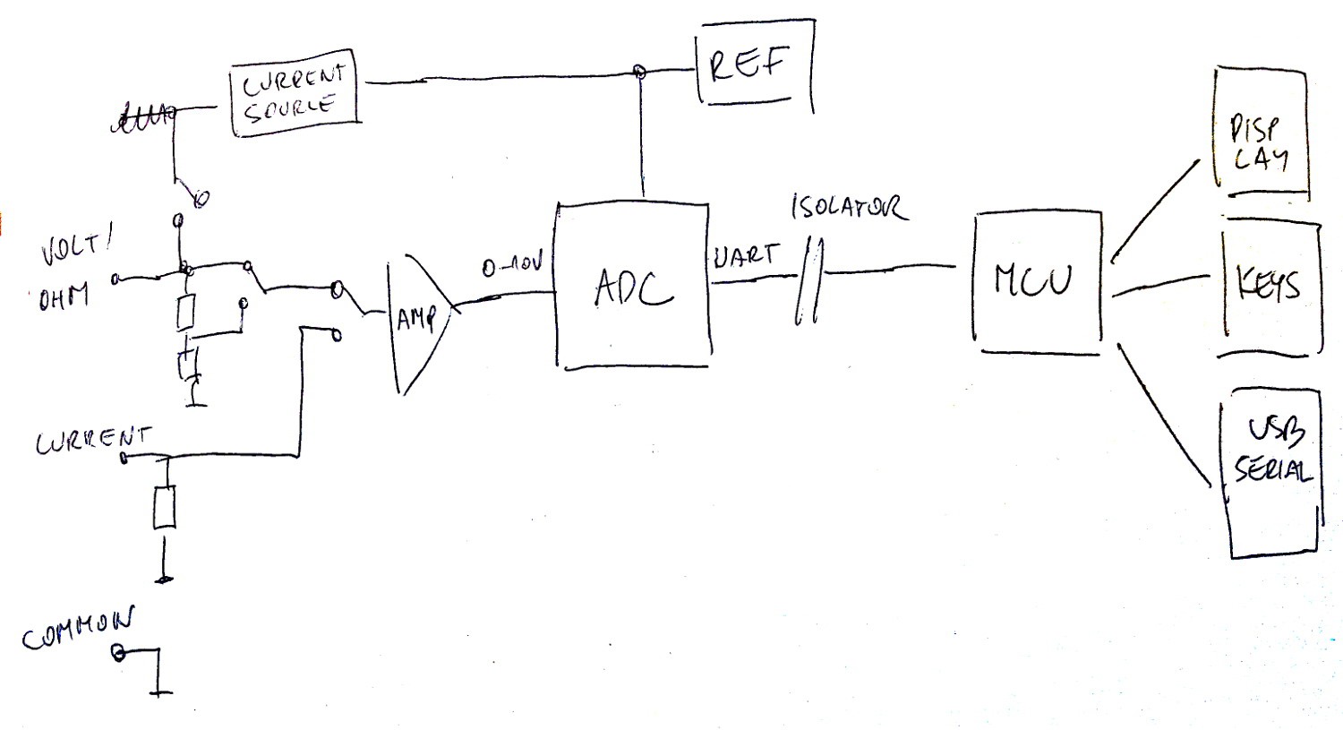
I designed 6-digit multimeter, capable of measuring voltage (1, 10 and 100V ranges), current (10mA and 100uA ranges, with separate 1A range) and resistance (1, 10, 100 and 1000kOhm). Project logs:
FAQ - answering typical questions
Basics - design sketches
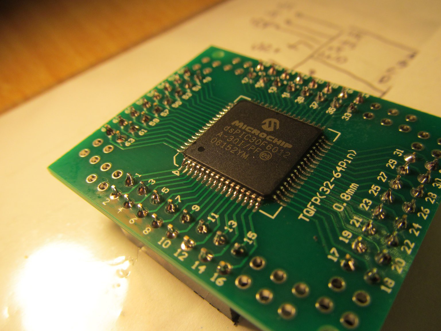
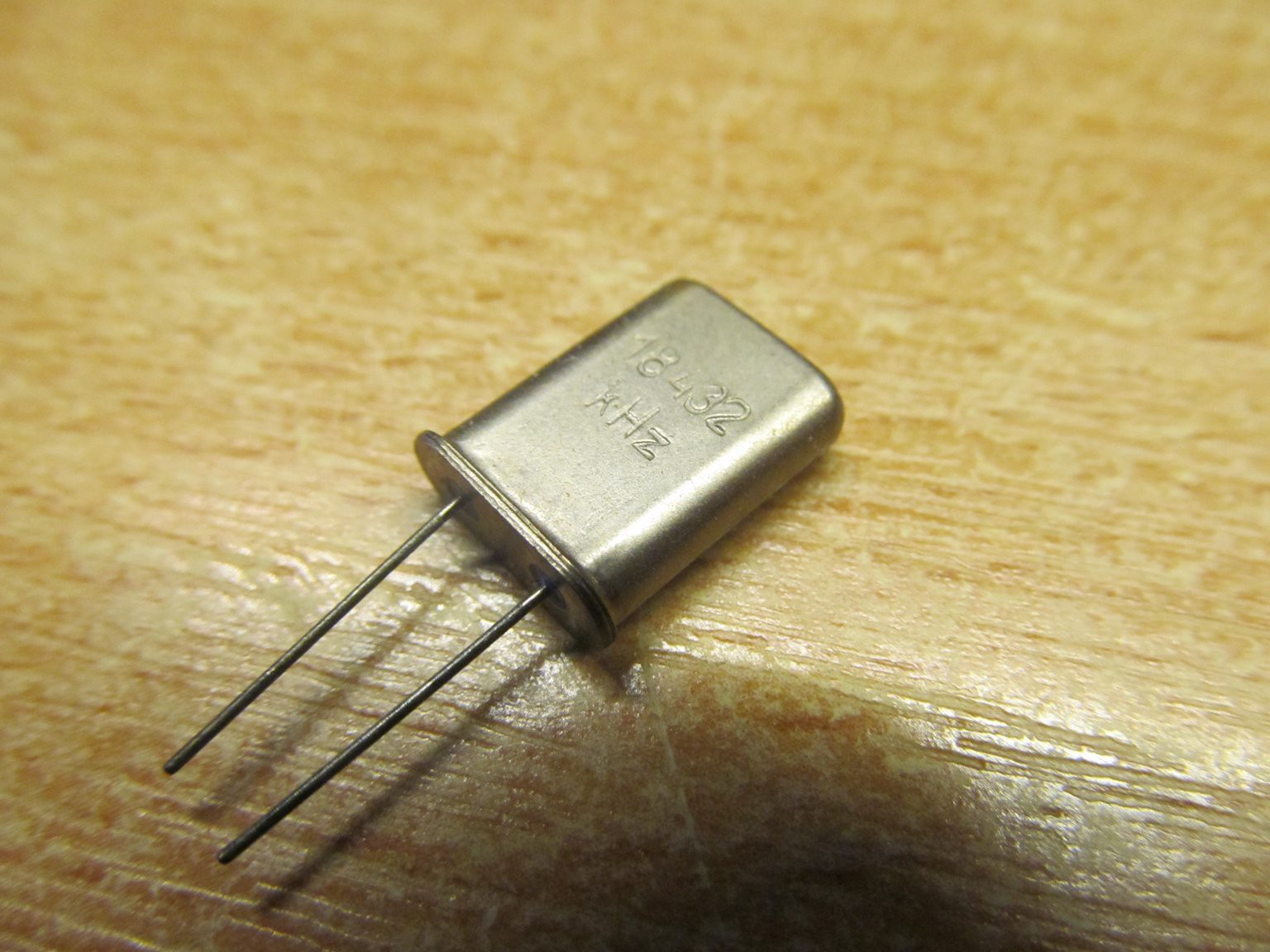
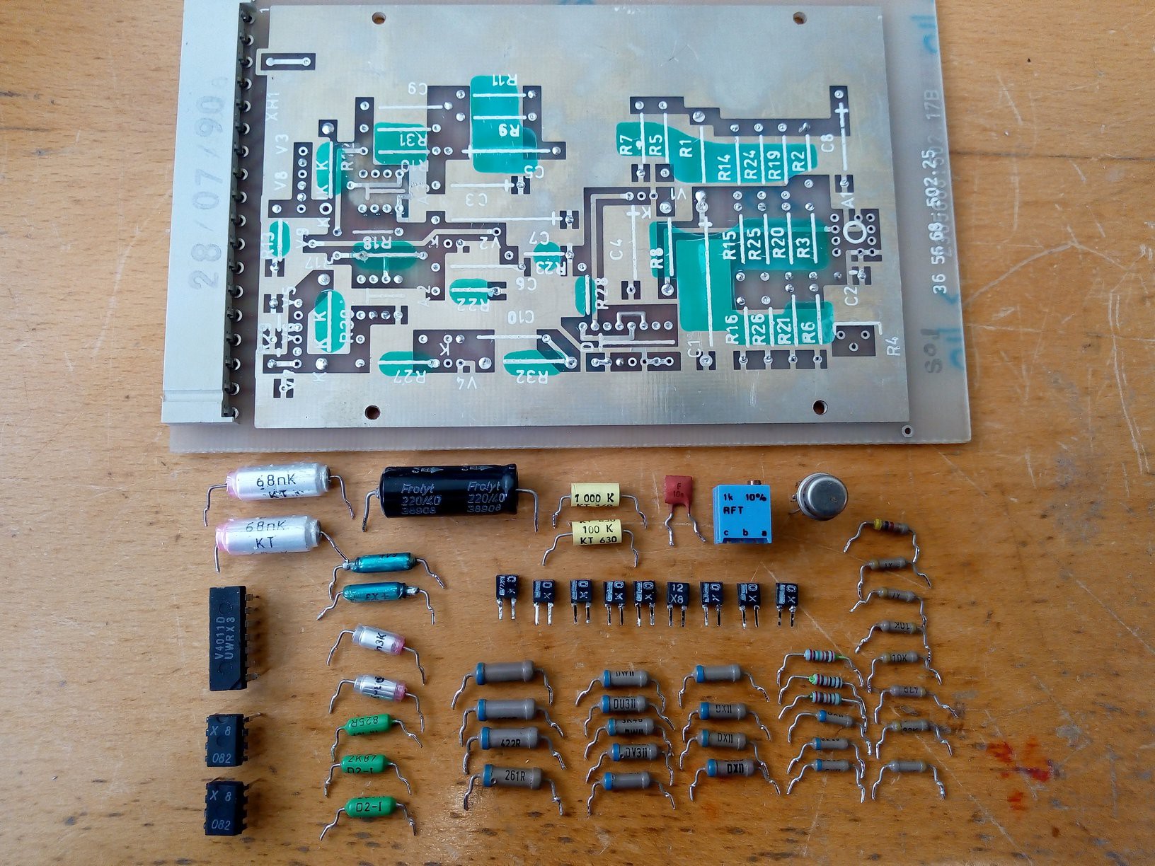
Design, part 1 - sourcing basic parts
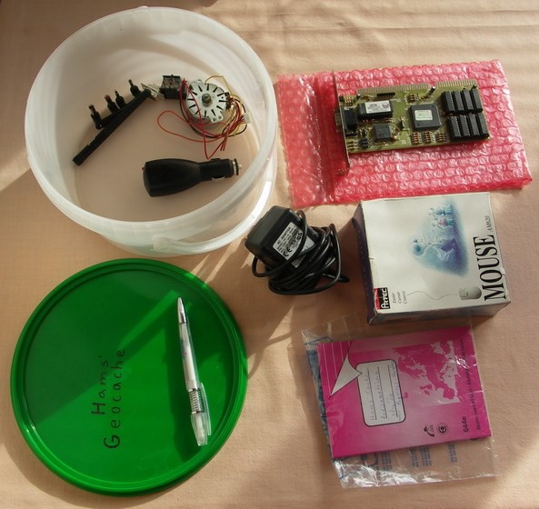
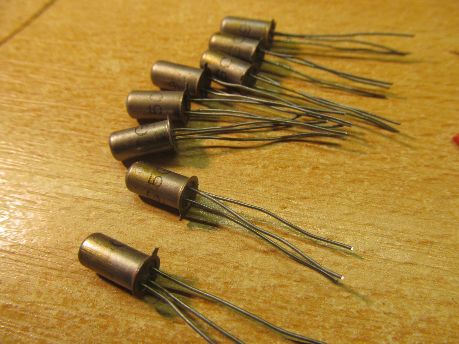
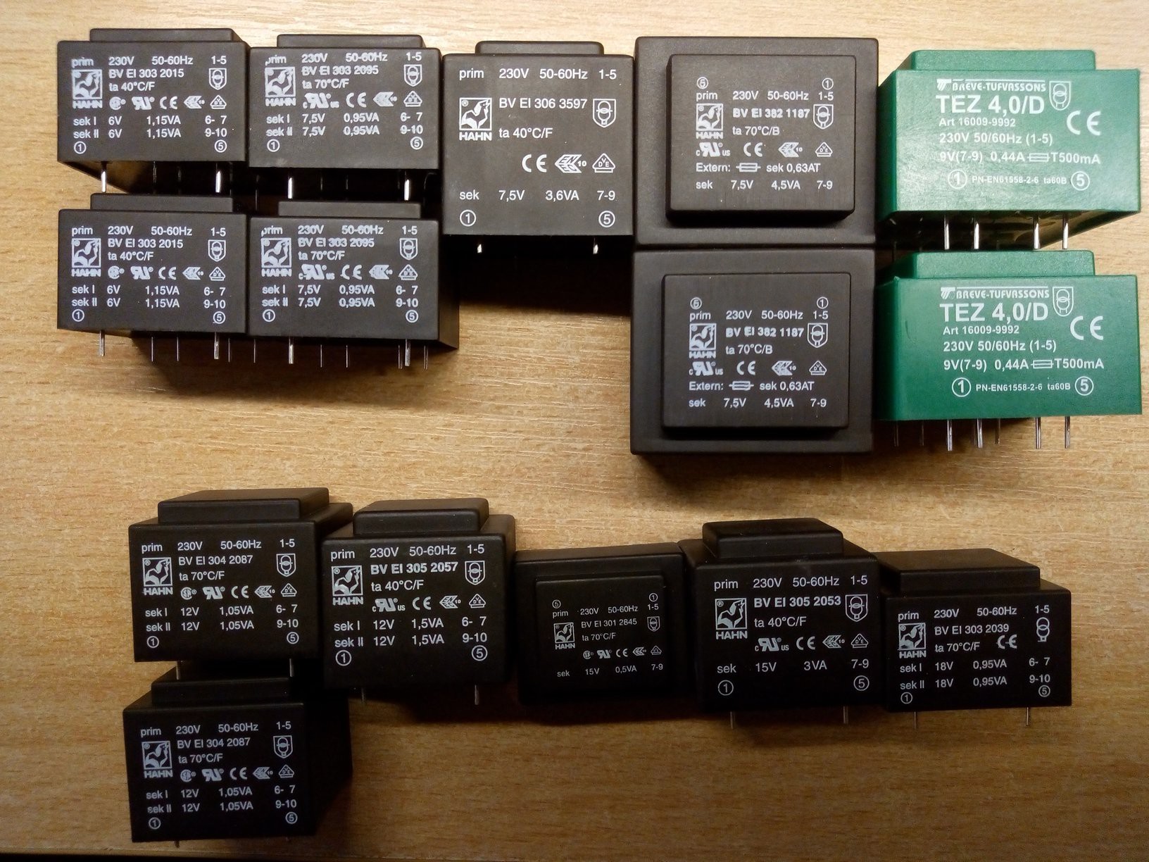
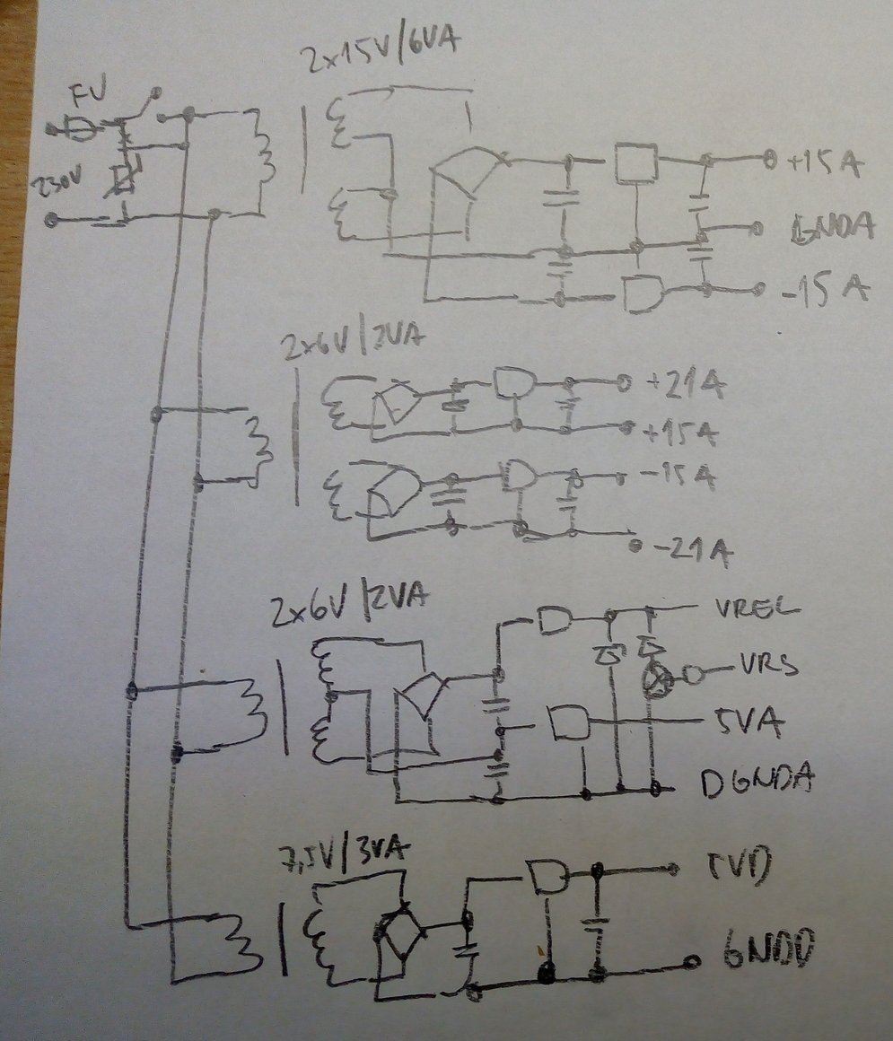
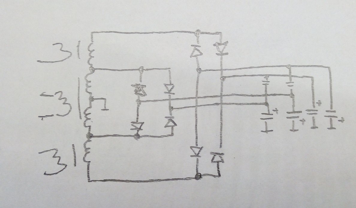
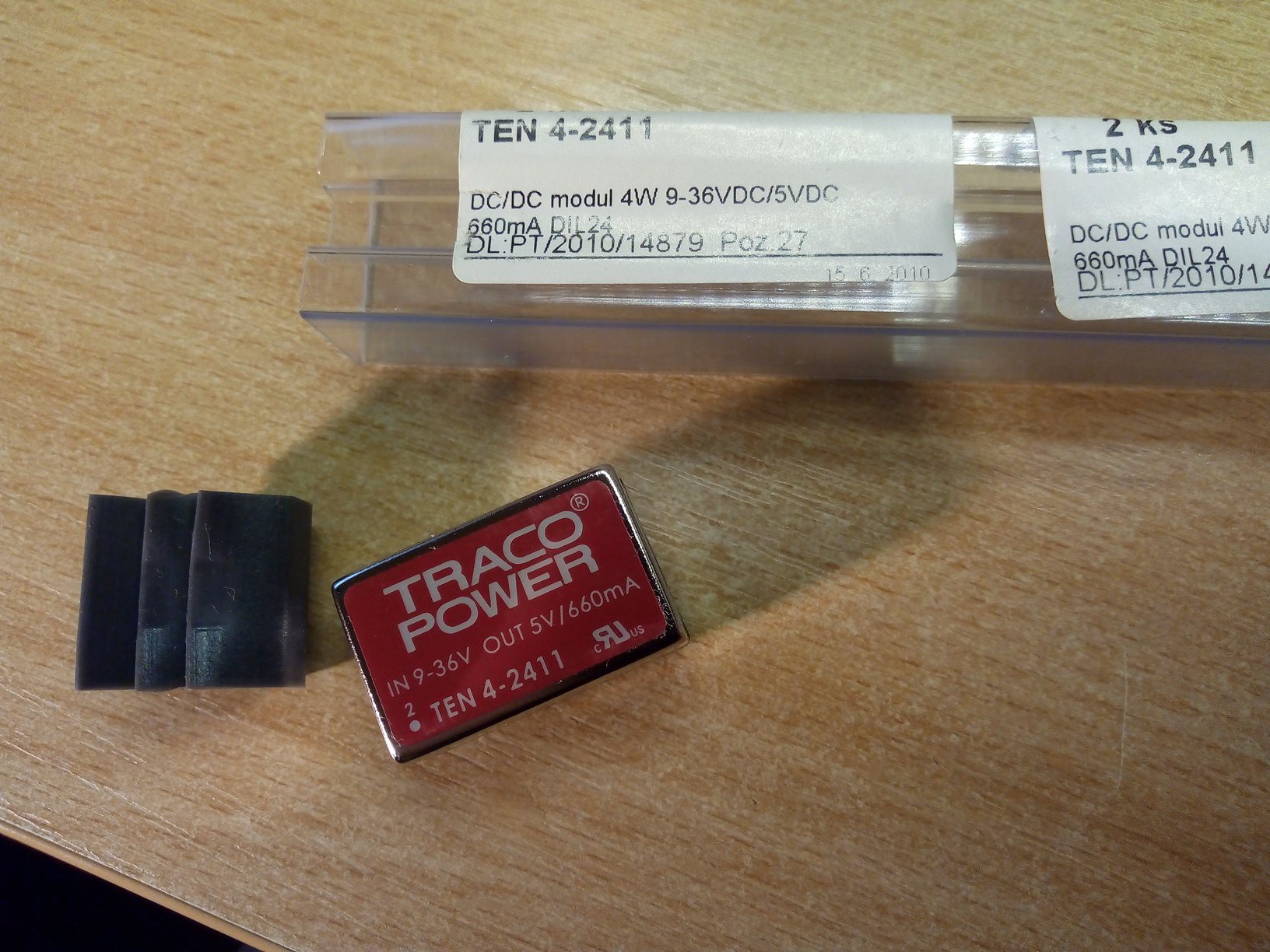
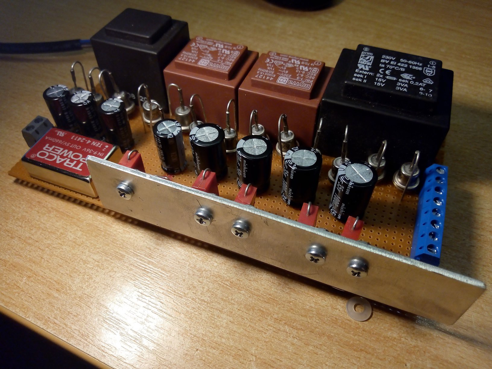
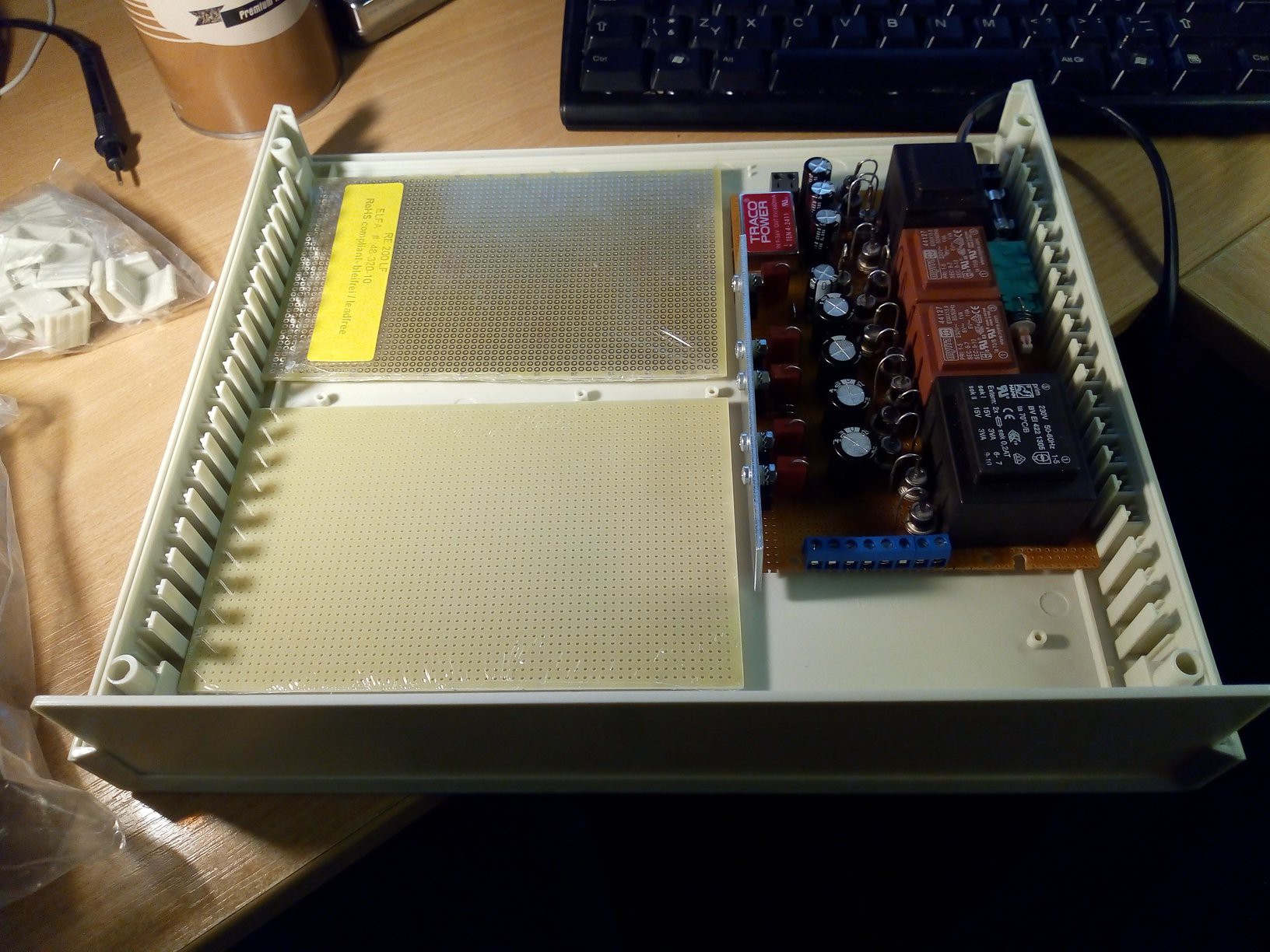
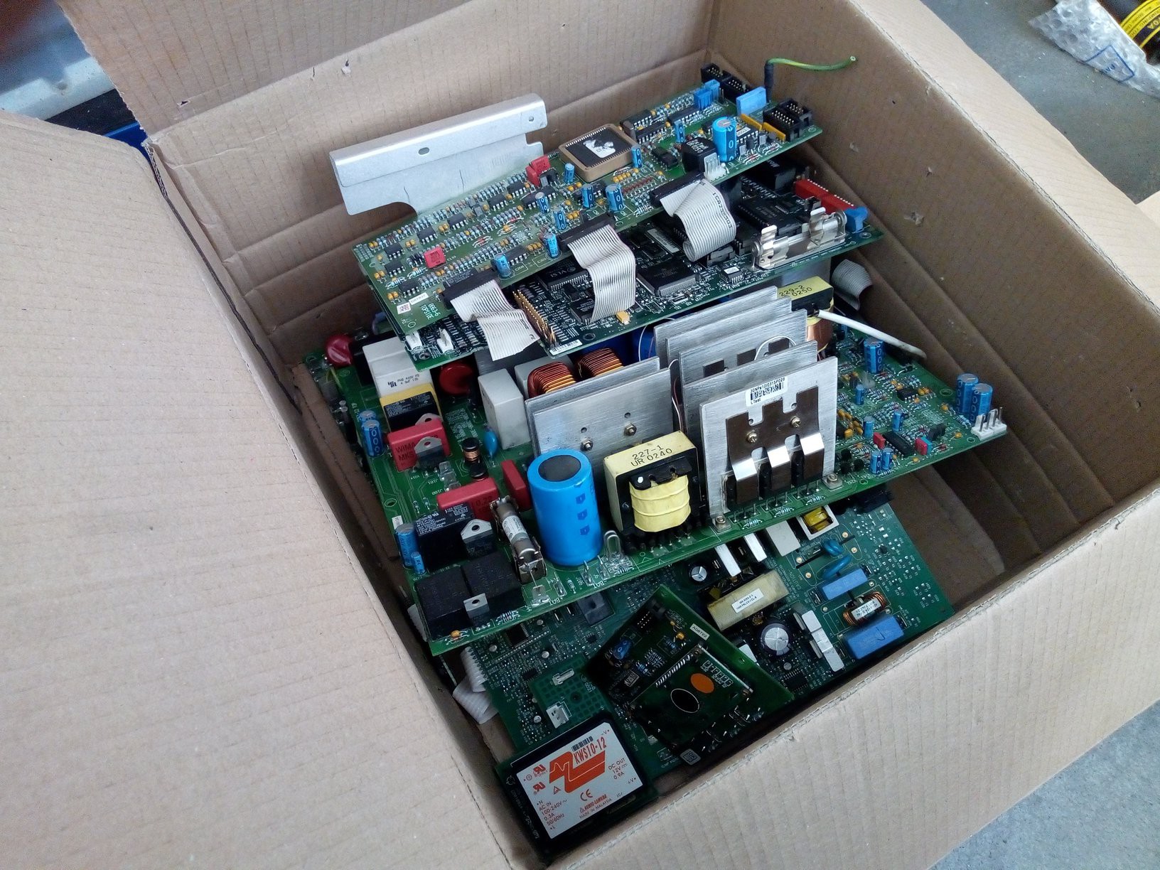
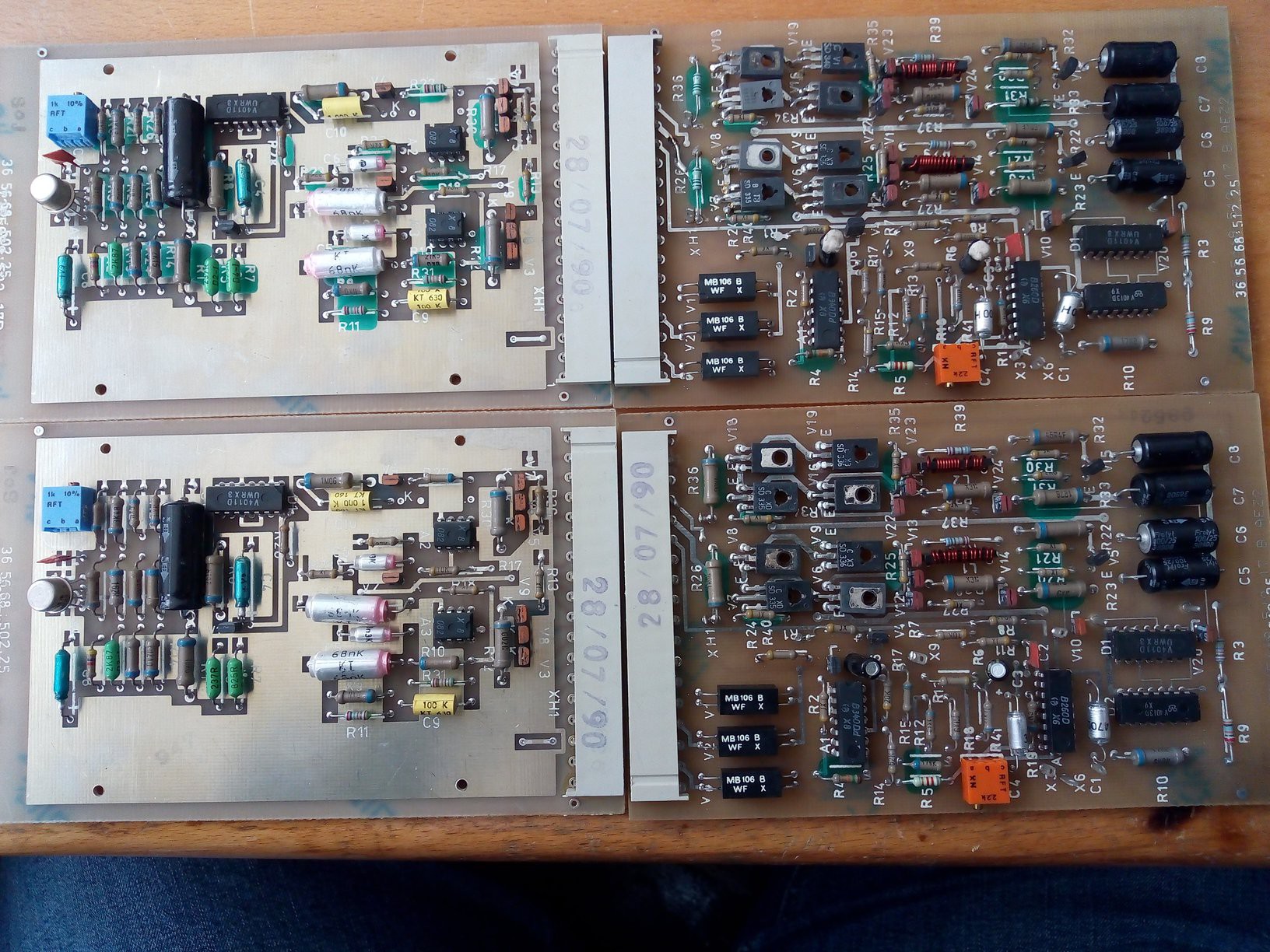
Design, part 2 - power supply, parts scavenging
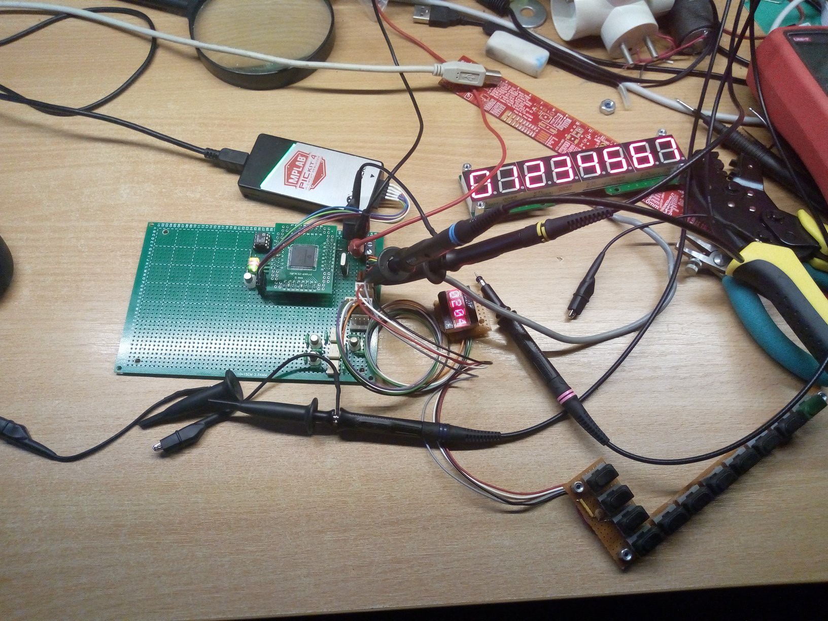
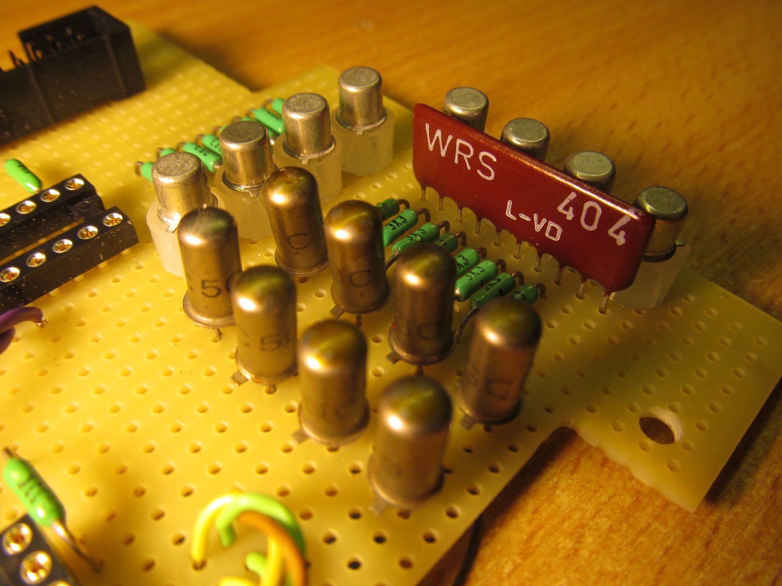
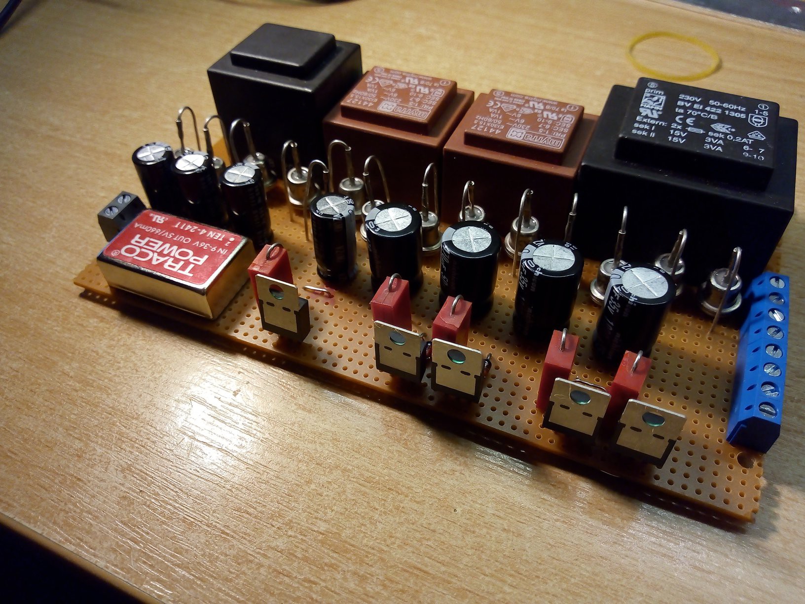
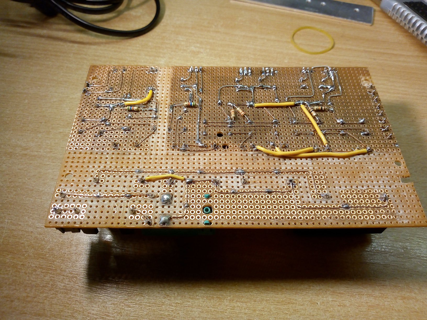
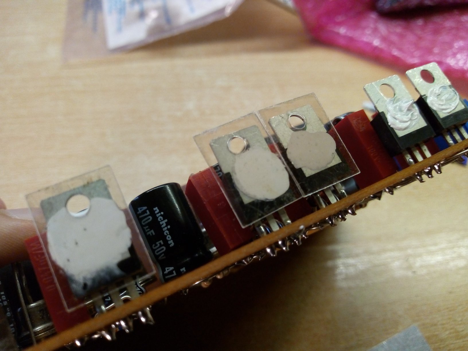
Design, part 3 - the real deal
Design, the end - final remarks
Short demonstration video
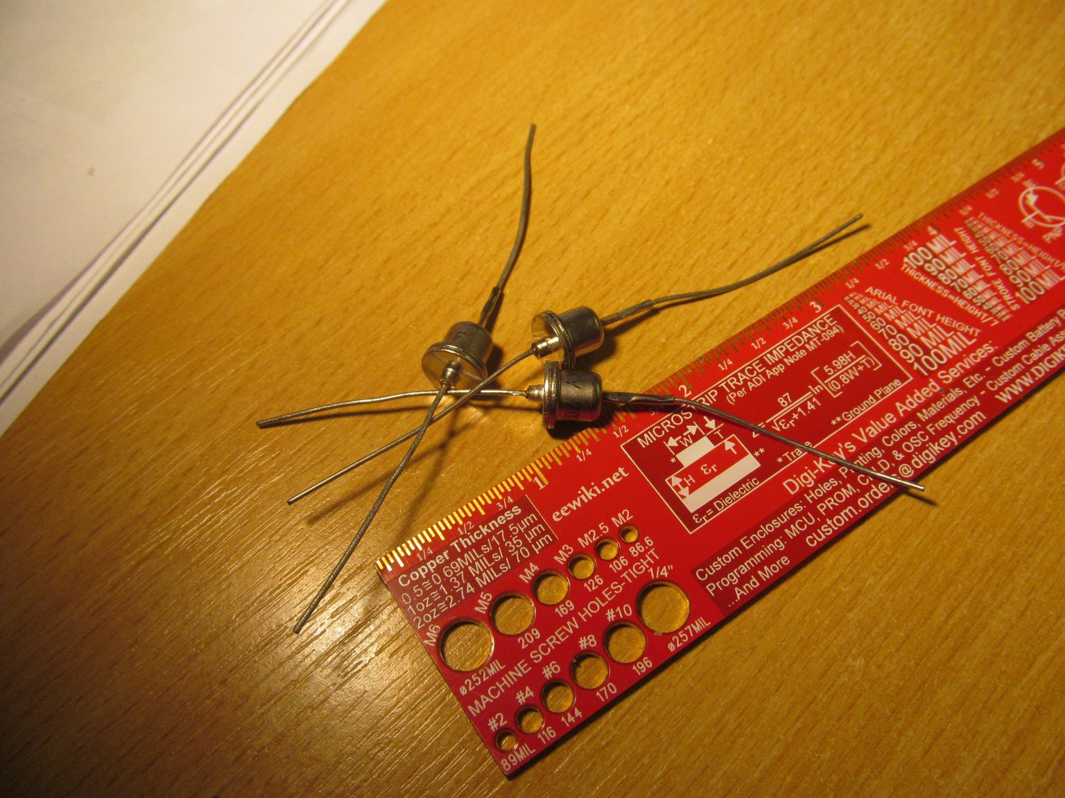
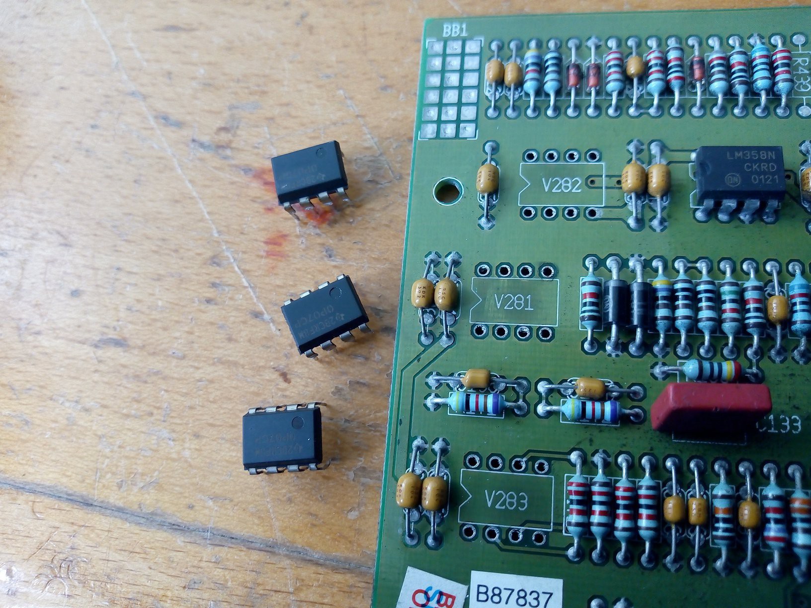
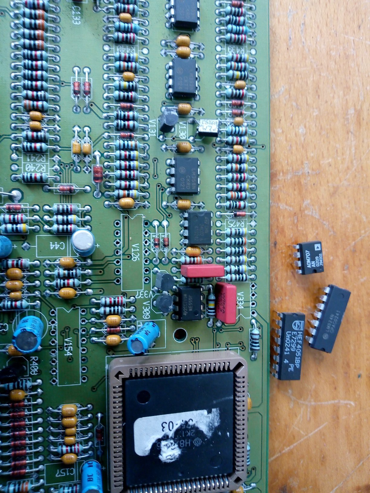
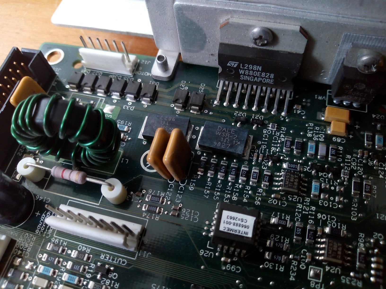
 Row of diodes
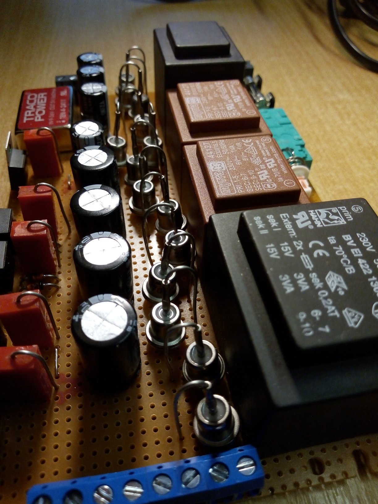


 2bluesc
 Mastro Gippo
Hello,
I really like your project and I think I can help you to make it.
Thankful