Project Overview
Many low cost robotics projects tend to use stepper motors, as they are easy to use to create precision applications. Small robots are often made with hobby servos, which allow for some level of position control. However, neither give the developer full control. Stepper motors only provide open loop position control, and can miss steps under load with no easy way to detect it. Hobby servos tend to be "jerky" and also typically provide no feedback to their actual position.
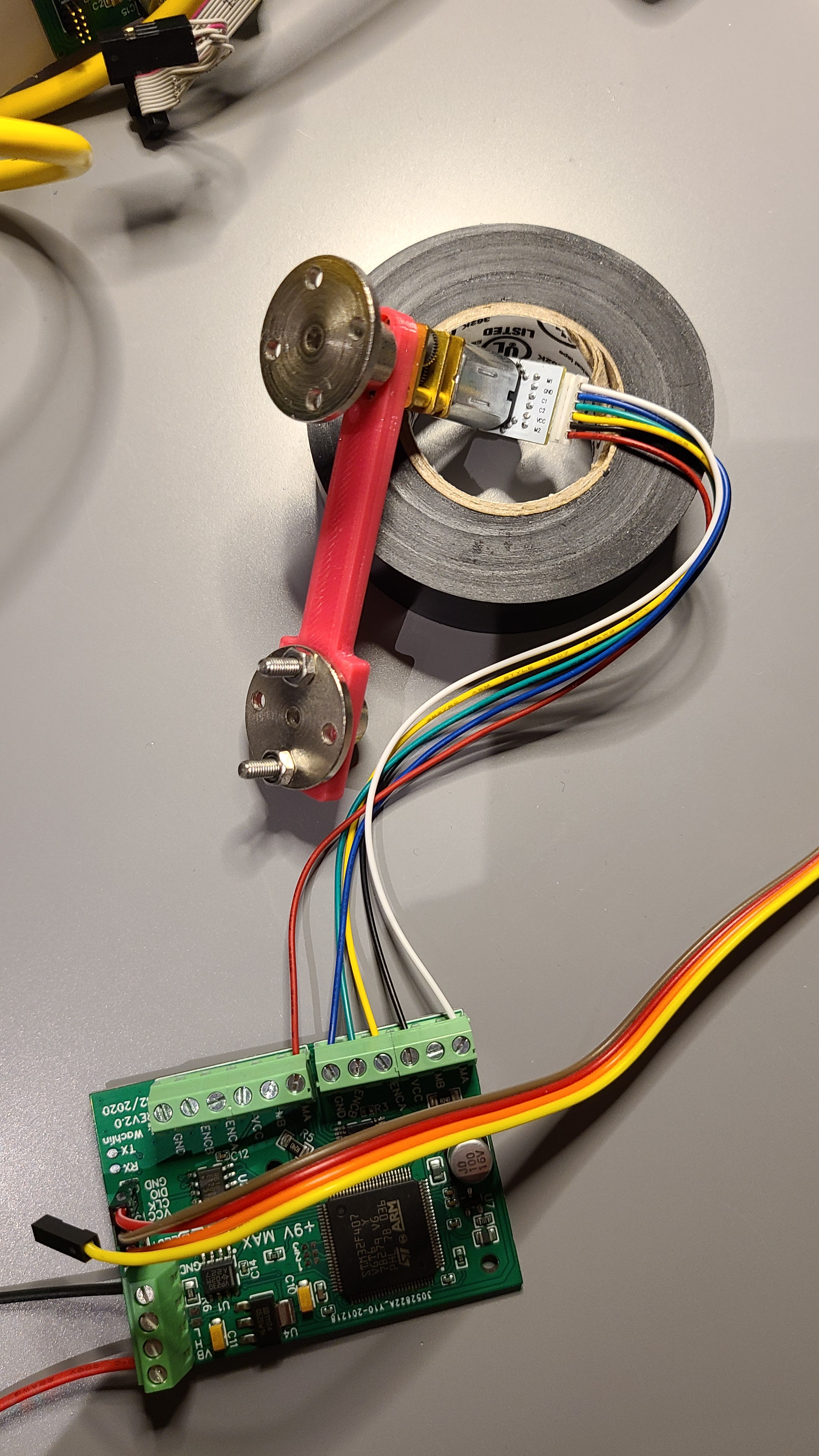
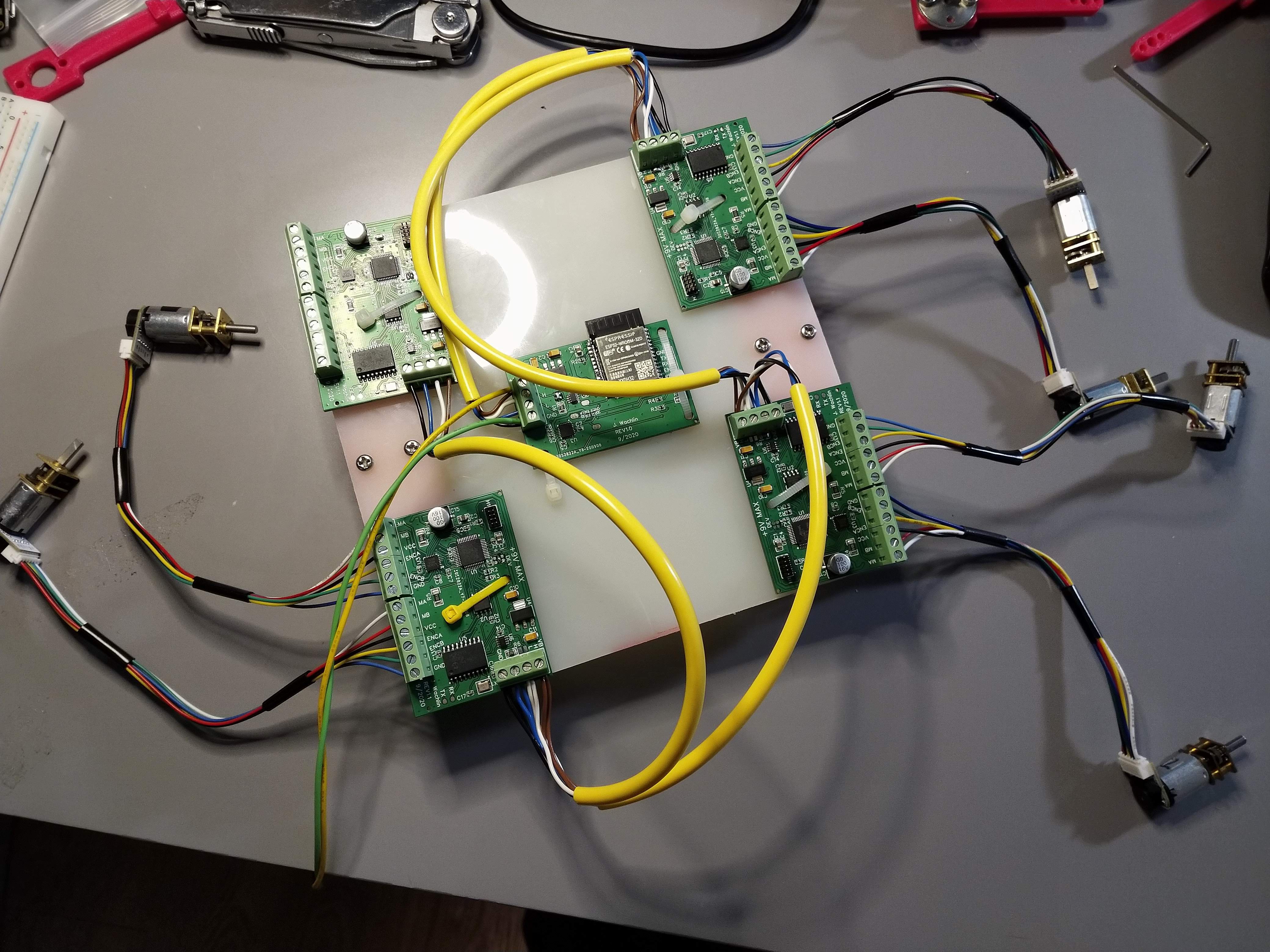
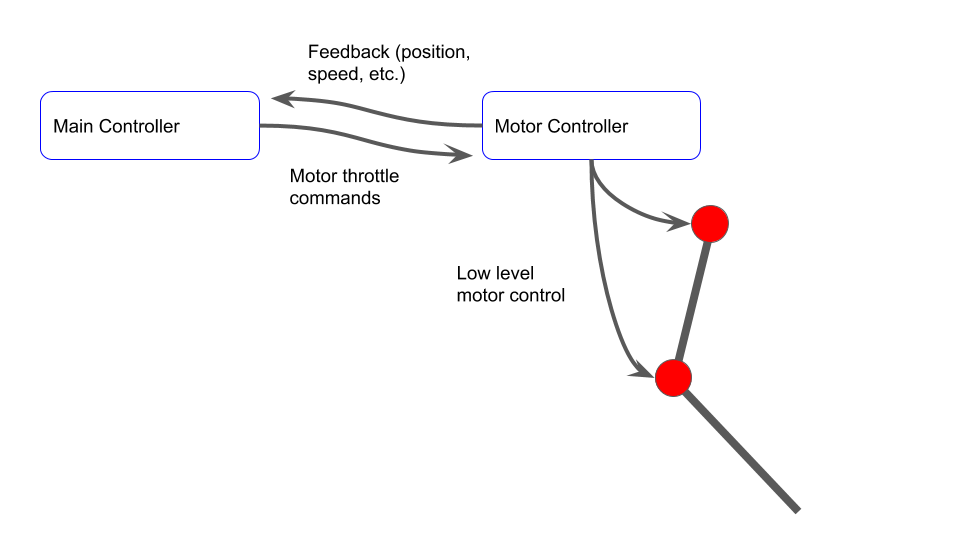
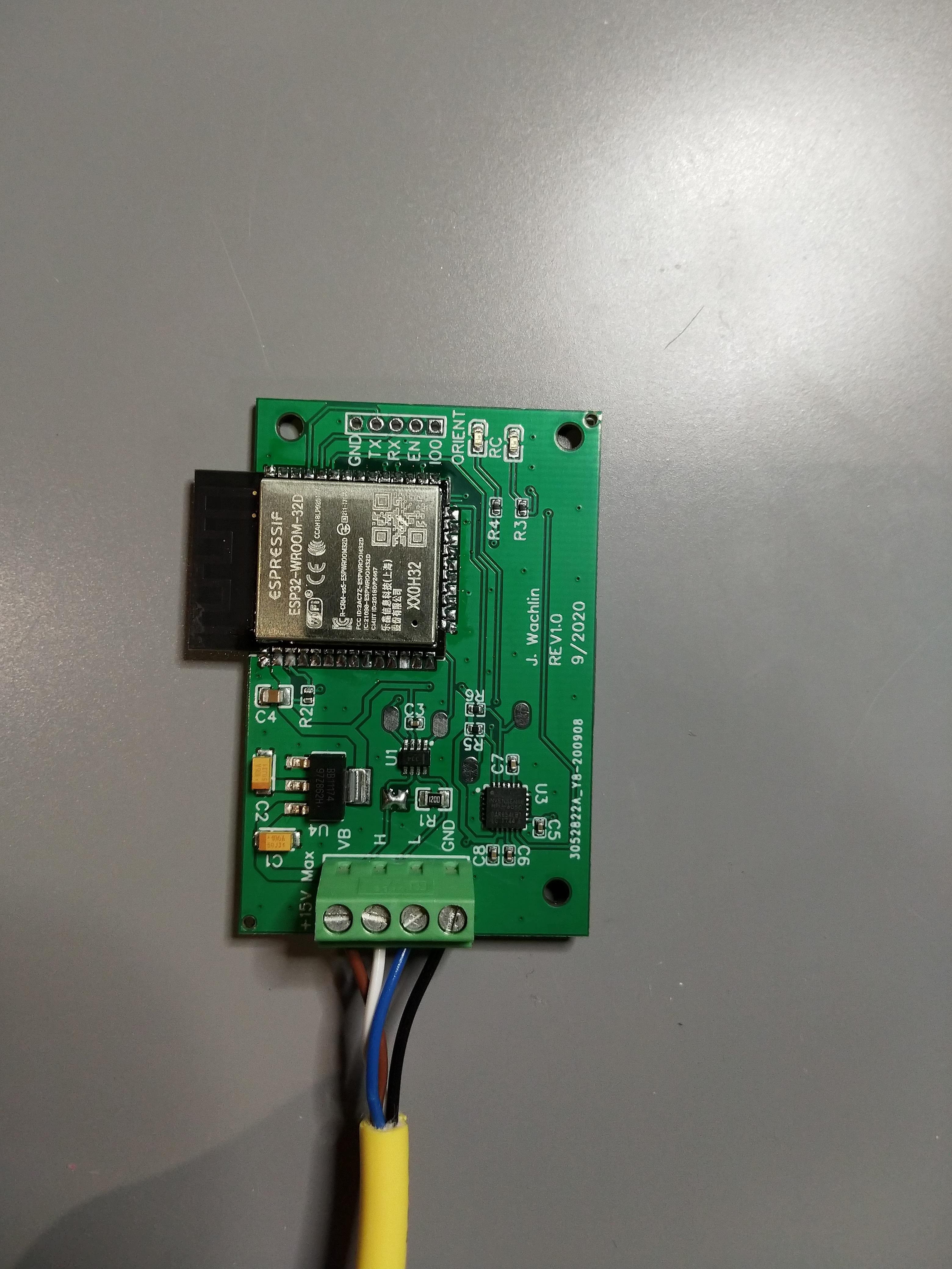
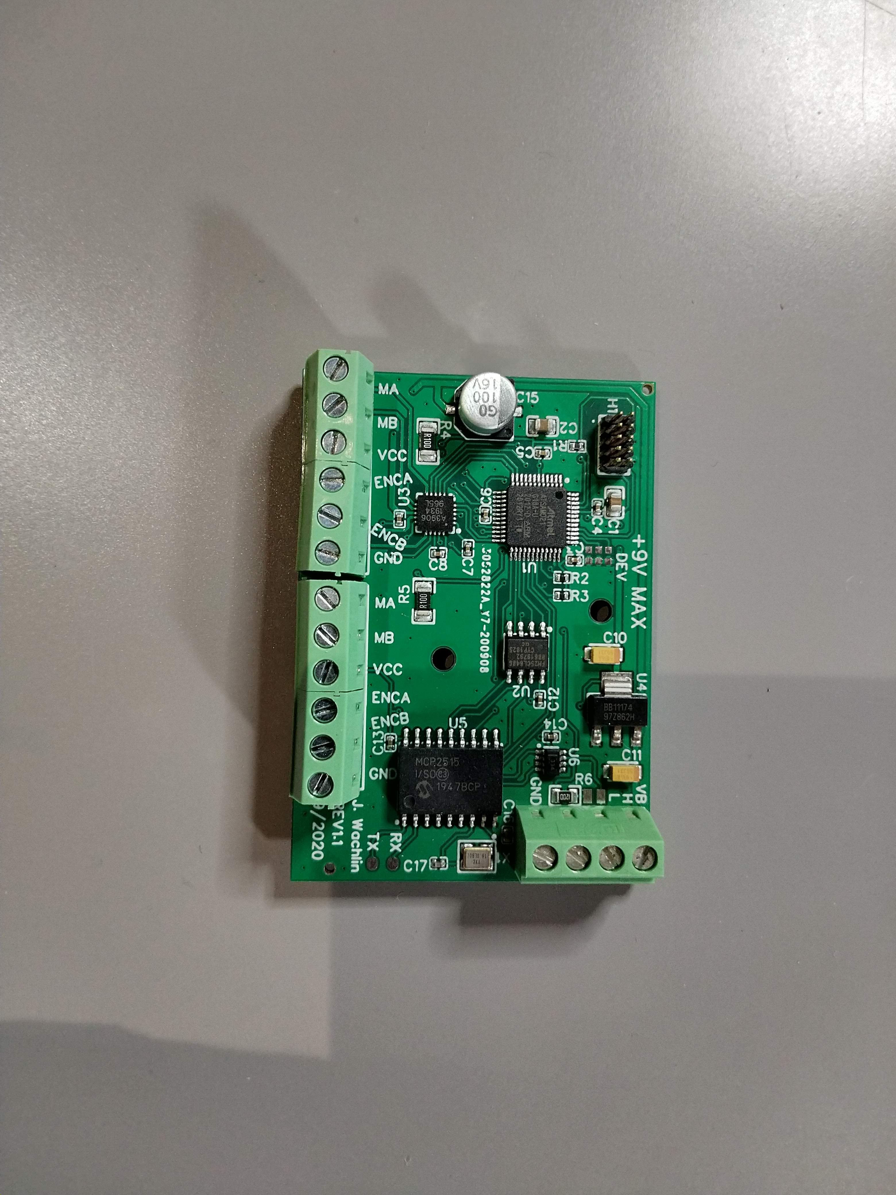
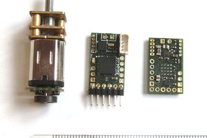
This project aims to develop a low-cost design which can be used for closed-loop control of two micro-gearmotors. The current to the motors will also be monitored for current limiting and possible impedance control applications. It can be interfaced with over CAN bus, ensuring robustness and scalability in robotics applications.
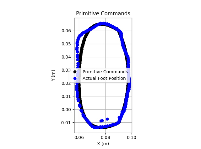
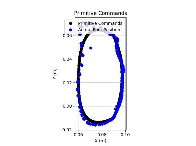
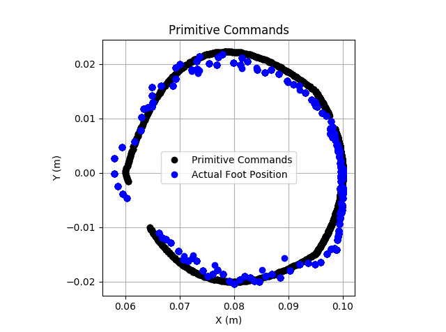
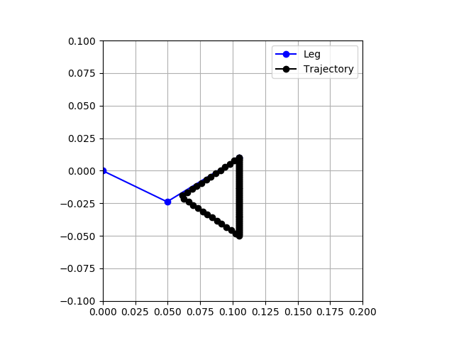
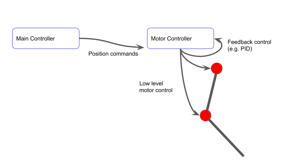
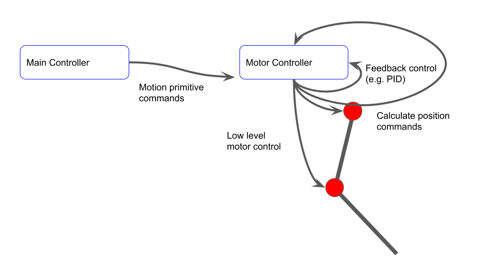
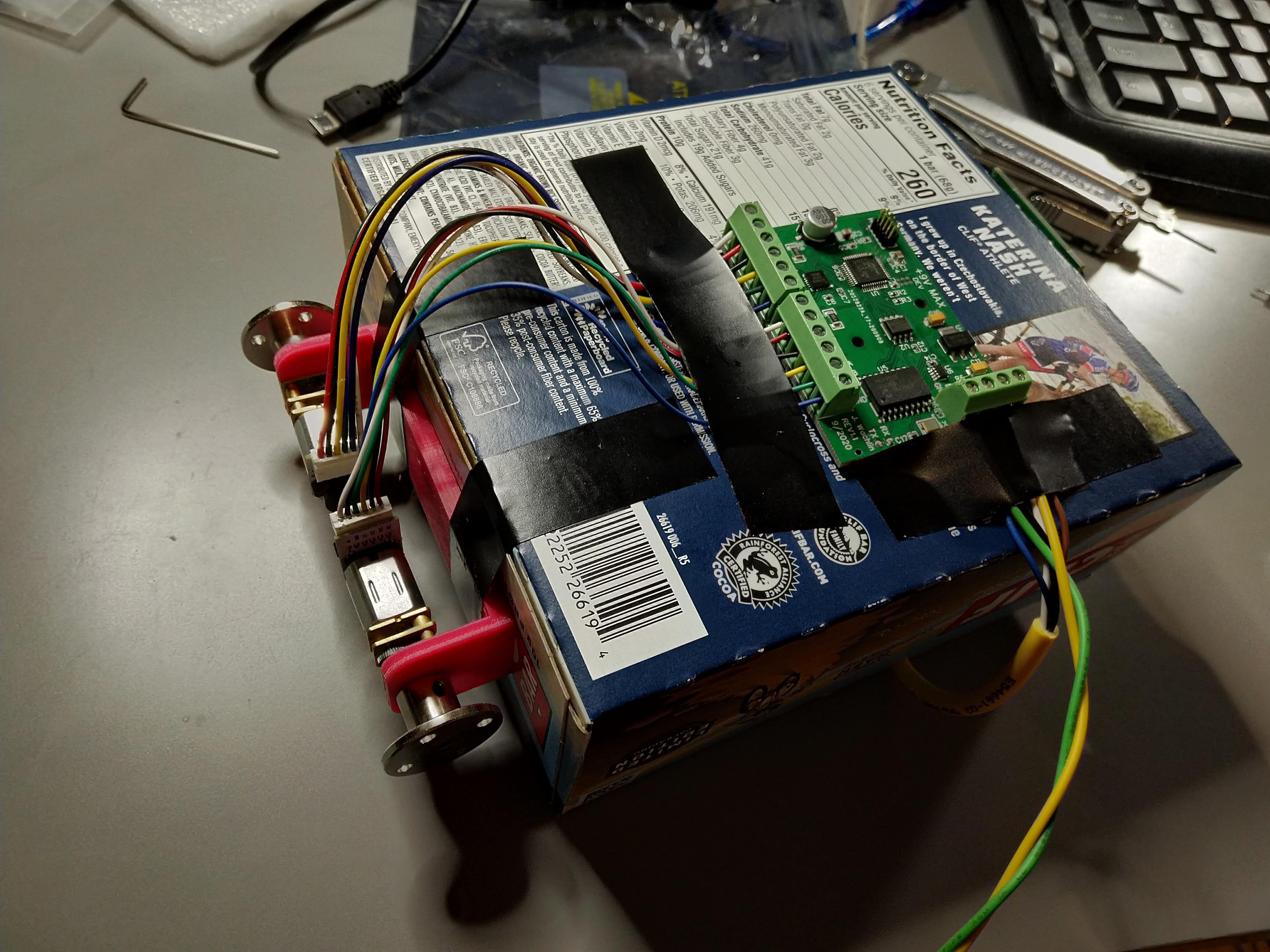
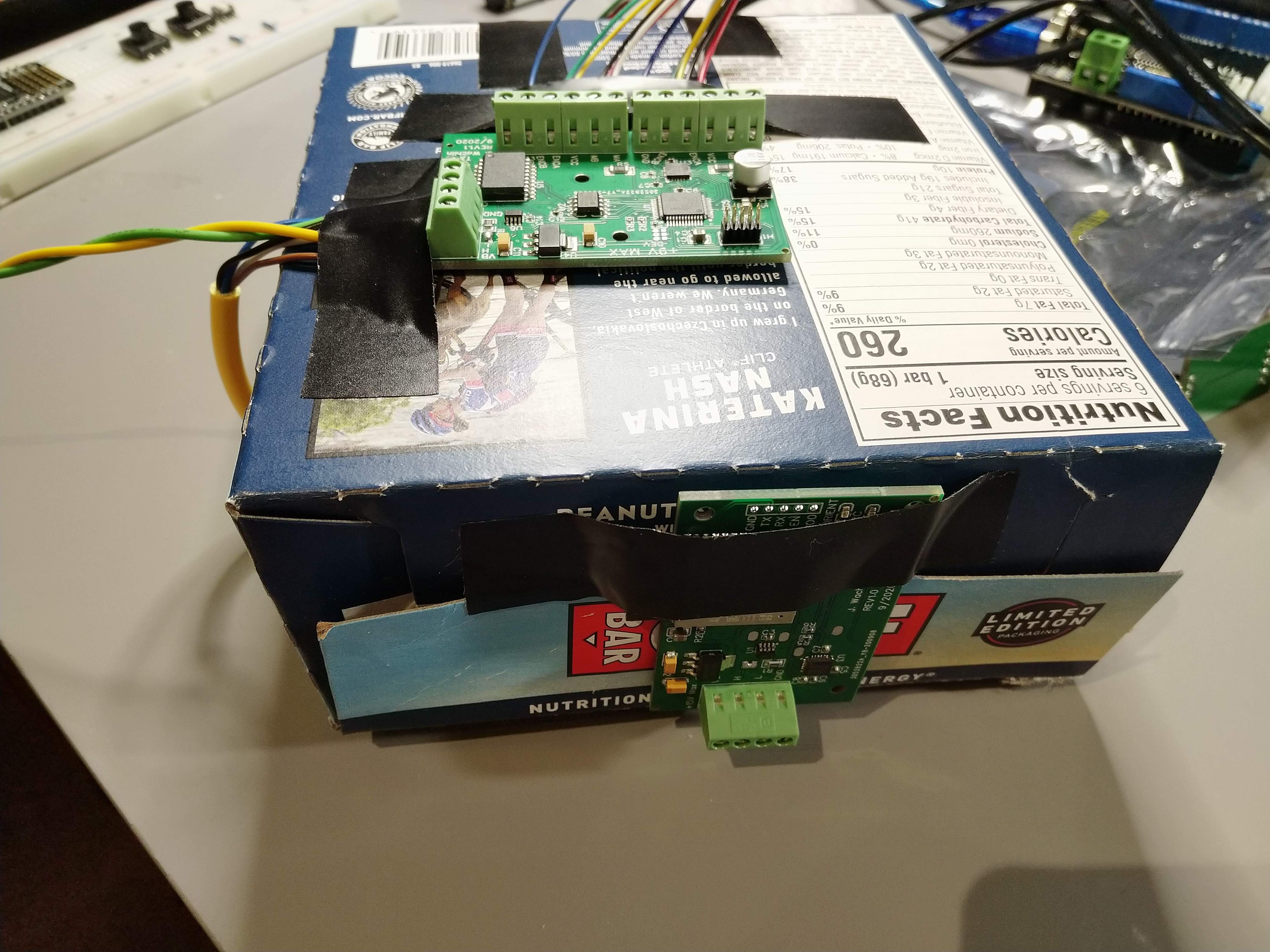
So far, this motor controller is capable of speed, position, current, and open loop duty cycle control. It supports motion primitives - motion profiles calculated using onboard inverse kinematics for walking robots that offload a main controller. They are highly configurable, with a CAN ICD detailing the external interface. I have developed (somewhat) working demos of a stabilized wheeled inverted pendulum, robotic legs, crawling robot, and recorded motion playback.
This project is closely linked to my build of a walking robot.
Covered by Hackster.io and Electronics-Labs.com.
Version 2 firmware available on GitHub.

Project Logs
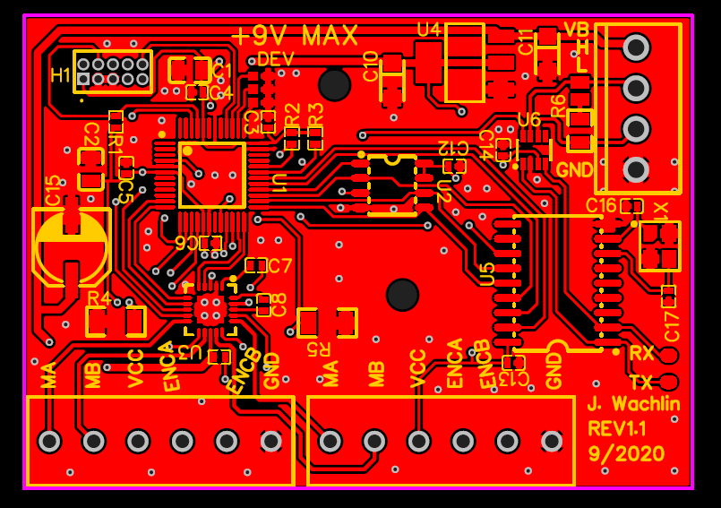
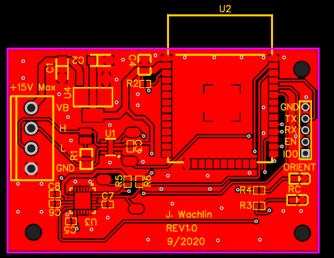
- Design
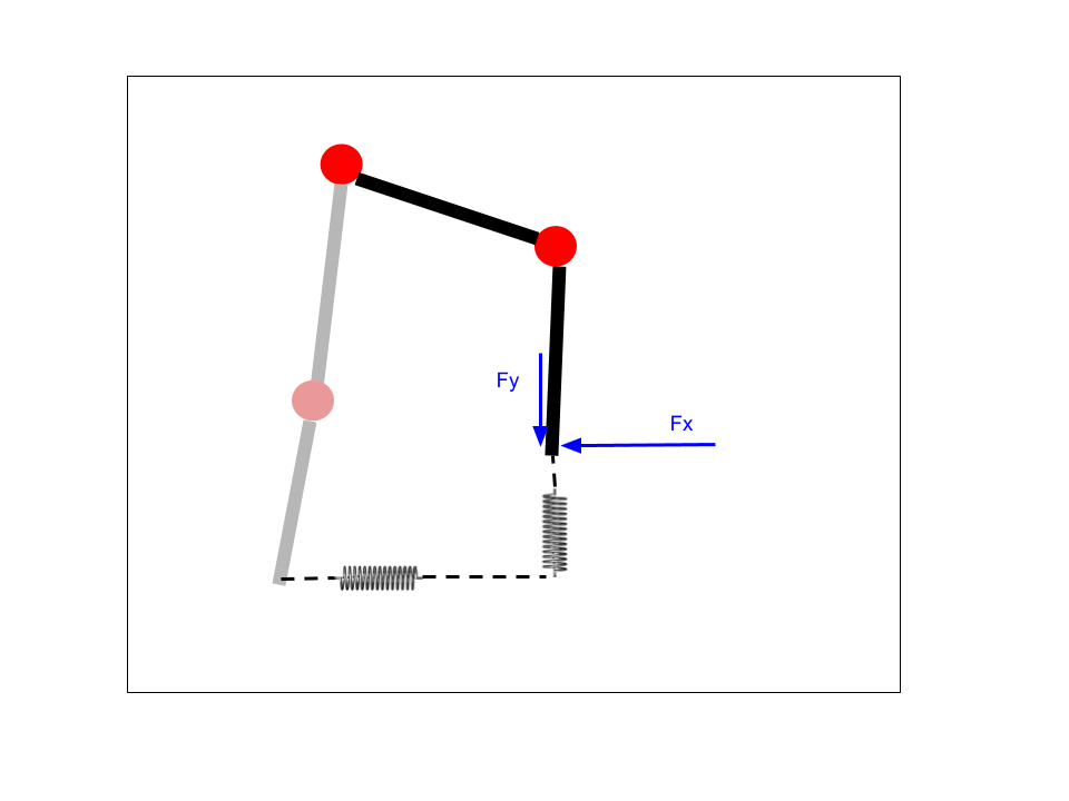
- Control and Inverse Kinematics
- Current Control and Virtual Model/Impedance Control
- CAN Bus Network
- Design Update
- Hardware Revision and Dumb Demo
- Motion Primitives
- CAN ICD, Quadruped Prep, and Motion Playback
- Quadruped Walking and Gait Testing
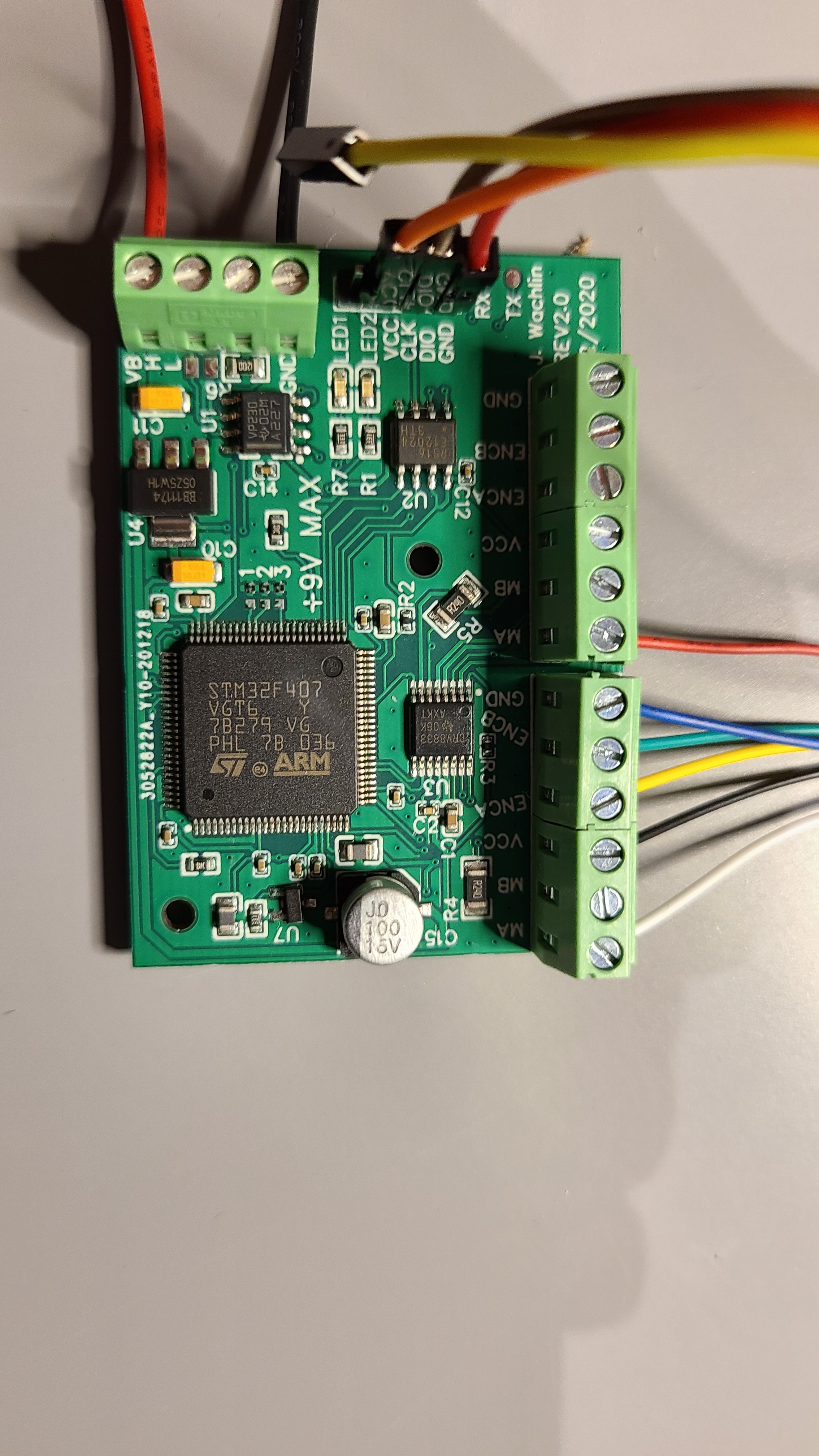
- Revision 2.0: Microcontroller Upgrade
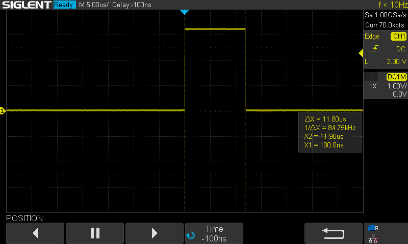
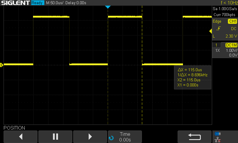
- Revision 2.0: Initial Testing
- Revision 2.0: CAN, Dual Motors, and Virtual Model Control

 Mayel Sorelus
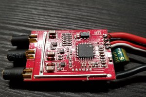
 Anthrobotics
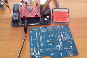
 sq7bti
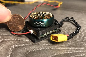
 Christopher Xu
FYI you can easily add a position feedback wire to any hobby servo. Open it up and solder on another wire where the potentiometer output pin connects to the control board. The board already has a resistor to make a voltage divider for its own reading of the position, so you can just run it straight to an ADC input pin on Arduino or whatever.
But servos are still imprecise, since the motor is either full on or full off, which makes for jerky motion and overshoot, which is dealt with by having a large "deadband" around the target position where it won't start up again until the target gets some distance away from the current position. So even if you gradually change the target position, it just results in repeated jerks rather than smooth motion.
But with the feedback wire you probably could do a little bit of current limiting/velocity control by using a servo that tolerates a wide voltage range, like SG90 can handle 3v to 7.2v. By switching to 3v supply when starting moving or approaching the target, you could get a little bit smoother movement. And the fact that it can survive 7.2v while starting up means you could probably push it to 12v or maybe even higher once it's up to speed. Would be interesting to experiment with.