 Dawid Buchwald
Putting it all together
After having completed implementation of my PLD-based address decoder, I finally decided to try and program it. Obviously I expected issues, because these were supposed to be programmed by dedicated hardware. I read about many, many issues with chips available on the market, so I came prepared. Got myself decent cup of coffee, locked myself and told my family to not disturb me for another three to four hours.
Grabbed my JED file, inserted ATF22V10 chip into my TL866 II+ and tried to guess proper minipro syntax:
dawid.buchwald@PL-2LGX4M2 ~/Documents/Personal/Development/6502/WinCUPL
$ ls -l
total 48
-rwx------+ 1 dawid.buchwald Domain Users 2777 Sep 10 15:40 DB6502.abs
-rwx------+ 1 dawid.buchwald Domain Users 4196 Sep 10 15:40 DB6502.doc
-rwx------+ 1 dawid.buchwald Domain Users 4261 Sep 10 15:40 DB6502.jed
-rwx------+ 1 dawid.buchwald Domain Users 3605 Sep 10 15:40 DB6502.pdf
-rwx------+ 1 dawid.buchwald Domain Users 2903 Sep 10 15:40 DB6502.PLD
-rwx------+ 1 dawid.buchwald Domain Users 1732 Sep 10 15:40 DB6502.si
-rwx------+ 1 dawid.buchwald Domain Users 1011 Sep 10 15:40 DB6502.sim
-rwx------+ 1 dawid.buchwald Domain Users 5287 Sep 10 15:40 DB6502.so
-rwx------+ 1 dawid.buchwald Domain Users 2343 Sep 10 15:40 DB6502.wo

dawid.buchwald@PL-2LGX4M2 ~/Documents/Personal/Development/6502/WinCUPL
$ minipro -p 'ATF22V10C' -w DB6502.jed
Found TL866II+ 04.2.112 (0x270)
Warning: Firmware is out of date.
  Expected  04.2.118 (0x276)
  Found     04.2.112 (0x270)

VPP=12V
Declared fuse checksum: 0x67A5 Calculated: 0x67A5 ... OK
Declared file checksum: 0x910D Calculated: 0x910D ... OK
JED file parsed OK

Use -P to skip write protect

Erasing... 0.33Sec OK
Writing jedec file...  5.01Sec  OK
Reading device...  0.41Sec  OK
Writing lock bit... 0.35Sec OK
Verification OK

dawid.buchwald@PL-2LGX4M2 ~/Documents/Personal/Development/6502/WinCUPL
$
Aaaaand that was it. Can't say I was disappointed to see it work the first time, but maybe I was? You know, just a little. I guess no troubleshooting for me now. Or so I thought.
Next step, obviously, was field testing the thing. The way I wanted to do this was to write simple Arduino program that would check all the possible combinations (64KB addresses accessed in 8 modes - CLK high/low, RW high/low, EXRAM high/low) and compare them against expected output.
I already implemented something similar in the past, but this time it was a bit more complicated. More vectors to test and a bit more outputs to verify.
The code I came up was along these lines:
#define IN_CLK         0
#define IN_RWB         1
#define IN_EXRAM       2

#define OUT_WEB        0
#define OUT_OEB        1
#define OUT_RAM1_CSB   2
#define OUT_RAM2_CSB   3
#define OUT_ROM_CSB    4
#define OUT_IO_CS      5

#define MODES_COUNT    3
#define ADDR_COUNT     16
#define OUTPUT_COUNT   6
#define MAX_FAIL       1000

const char MODES[]   = {53, 51, 49};
const char ADDR[]    = {52, 50, 48, 46, 44, 42, 40, 38, 36, 34, 32, 30, 28, 26, 24, 22};
const char OUTPUTS[] = {47, 45, 43, 41, 39, 37};

uint16_t BIT_MASK[ADDR_COUNT];

bool ADDR_VAL[ADDR_COUNT];

uint16_t currentAddress;
uint8_t  currentMode;
uint8_t  currentOutput;

uint32_t passCount;
uint32_t failCount;

void setup() {
  setupPinModes();
  Serial.begin(57600);
  runTest();
  displayTestResult();
}

void setupPinModes() {
  uint8_t i;

  for (i=0; i<ADDR_COUNT; i++) {
    pinMode(ADDR[i], OUTPUT);
    digitalWrite(ADDR[i], LOW);
    ADDR_VAL[i]=false;
    BIT_MASK[i]=1 << i;
  }

  for (i=0; i<MODES_COUNT; i++) {
    pinMode(MODES[i], OUTPUT);
    digitalWrite(MODES[i], LOW);
  }

  for (i=0; i<OUTPUT_COUNT; i++) {
    pinMode(OUTPUTS[i], INPUT);
  }
}

void loop() {
}
This is basic init - setting Arduino pins to input/output, populating basic values (like bitmask) and so on. Nothing fancy here.
This is also pretty basic:
void displayTestResult() {
  char output[128];
  Serial.println("Test results:");
  sprintf(output, " Scenarios passed: %lu", passCount);
  Serial.println(output);
  sprintf(output, " Scenarios failed: %lu", failCount);
  Serial.println(output);
  Serial.println("-------------------------------");
}
It summarizes test results and sends them to serial monitor.
void runTest() {
  currentAddress = 0x0000;
  passCount = 0;
  failCount = 0;
  Serial.println();
  Serial.println("-------------------------------");
  Serial.println("Address decoder testing utility");
  Serial.print("Testing");
  while (true) {
    if (! (currentAddress & 0x07ff)) {
      Serial.print(".");
    }
    testAddress(currentAddress);
    if (currentAddress == 0xffff) {
      break;
    }
    currentAddress++;
  }
  Serial.println("done.");
}
Actual testing is also pretty simple. The only addition here is that I display one dot for each 0x0800 addresses just to indicate that the thing is alive. I expected it to be pretty slow.
For each address to be tested we need to run 8 scenarios for each combination of CLK, RW and EXROM pins:
void testAddress(uint16_t address) {
  setAddress(address);
  uint8_t modeVariants = 1 << MODES_COUNT;
  uint8_t outputs;
  for (currentMode = 0; currentMode<modeVariants; currentMode++) {
    setMode(currentMode);
    outputs=readOutputs();
    if (verifyOutputs(address, currentMode, outputs)) {
      passCount++;
    } else {
      failCount++;
      if (failCount < MAX_FAIL) {
        char message[128];
        Serial.println();
        sprintf(message, " Test failed at address %04x, in mode %02x, resulting in output %02x", address, currentMode, outputs);
        Serial.println(message);
      }
    }
  }
}
There are some helper functions, like setAddress, that changes state of Arduino pins only if the expected value is already different - this optimization prevents too many digitalWrite operations, which are extremely slow.
void setAddress(uint16_t address) {
  for(uint8_t i=0; i<ADDR_COUNT; i++) {
    bool bit =  address & BIT_MASK[i];
    if (bit != ADDR_VAL[i]) {
      digitalWrite(ADDR[i], bit ? HIGH : LOW);
      ADDR_VAL[i] = bit;
    }
  }
}
Now, I should have probably used direct port access, that would be much faster, but I didn't really want to bother with Arduino Mega wiring - it's insane how there ports are mapped to pins.
For all the possible modes I didn't bother with the optimization:
void setMode(uint8_t mode) {
  for(uint8_t i=0; i<MODES_COUNT; i++) {
    bool bit =  mode & BIT_MASK[i];
    digitalWrite(MODES[i], bit ? HIGH : LOW);
  }
}
Reading outputs - trivial again. Would be even easier if I used ports directly, but whatever:
uint8_t readOutputs() {
  uint8_t result=0;
  for (uint8_t i=0; i<OUTPUT_COUNT; i++) {
    if (digitalRead(OUTPUTS[i])) {
      result += BIT_MASK[i];
    }
  }
  return result;
}
And finally the function to verify the outputs:
bool verifyOutputs(uint16_t address, uint8_t mode, uint8_t outputs) {
  bool clk     = mode & BIT_MASK[IN_CLK];
  bool rwb     = mode & BIT_MASK[IN_RWB];
  bool exram   = mode & BIT_MASK[IN_EXRAM];
  bool web     = outputs & BIT_MASK[OUT_WEB];
  bool oeb     = outputs & BIT_MASK[OUT_OEB];
  bool ram1Csb = outputs & BIT_MASK[OUT_RAM1_CSB];
  bool ram2Csb = outputs & BIT_MASK[OUT_RAM2_CSB];
  bool romCsb  = outputs & BIT_MASK[OUT_ROM_CSB];
  bool ioCs    = outputs & BIT_MASK[OUT_IO_CS];

  bool ram1    = (address <= 0x7fff);
  bool ram2    = (address >= 0x8000 && address <= 0xbfff);
  bool rom     = (address >= 0xc000 && address <= 0xffff);
  bool io      = (address >= 0x0200 && address <= 0x02ff);

  bool exp_web     = !(clk && !rwb);
  bool exp_oeb     = !(clk && rwb);
  bool exp_ram1Csb = !(ram1 && !io);
  bool exp_ram2Csb = !(exram && ram2);
  bool exp_romCsb  = !(rom || (!exram && ram2));
  bool exp_ioCs    = io;

  return (web     == exp_web) &&
         (oeb     == exp_oeb) &&
         (ram1Csb == exp_ram1Csb) &&
         (ram2Csb == exp_ram2Csb) &&
         (romCsb  == exp_romCsb) &&
         (ioCs    == exp_ioCs);
}
Same problem here - I calculate all the expected and actual values the slowest possible way, but what I was going for was clarity. I wanted the code easy to read and maintain.
Finally, I plugged ATF22V10 into breadboard and connected to Arduino Mega using special ribbons I made for my 6502 build:
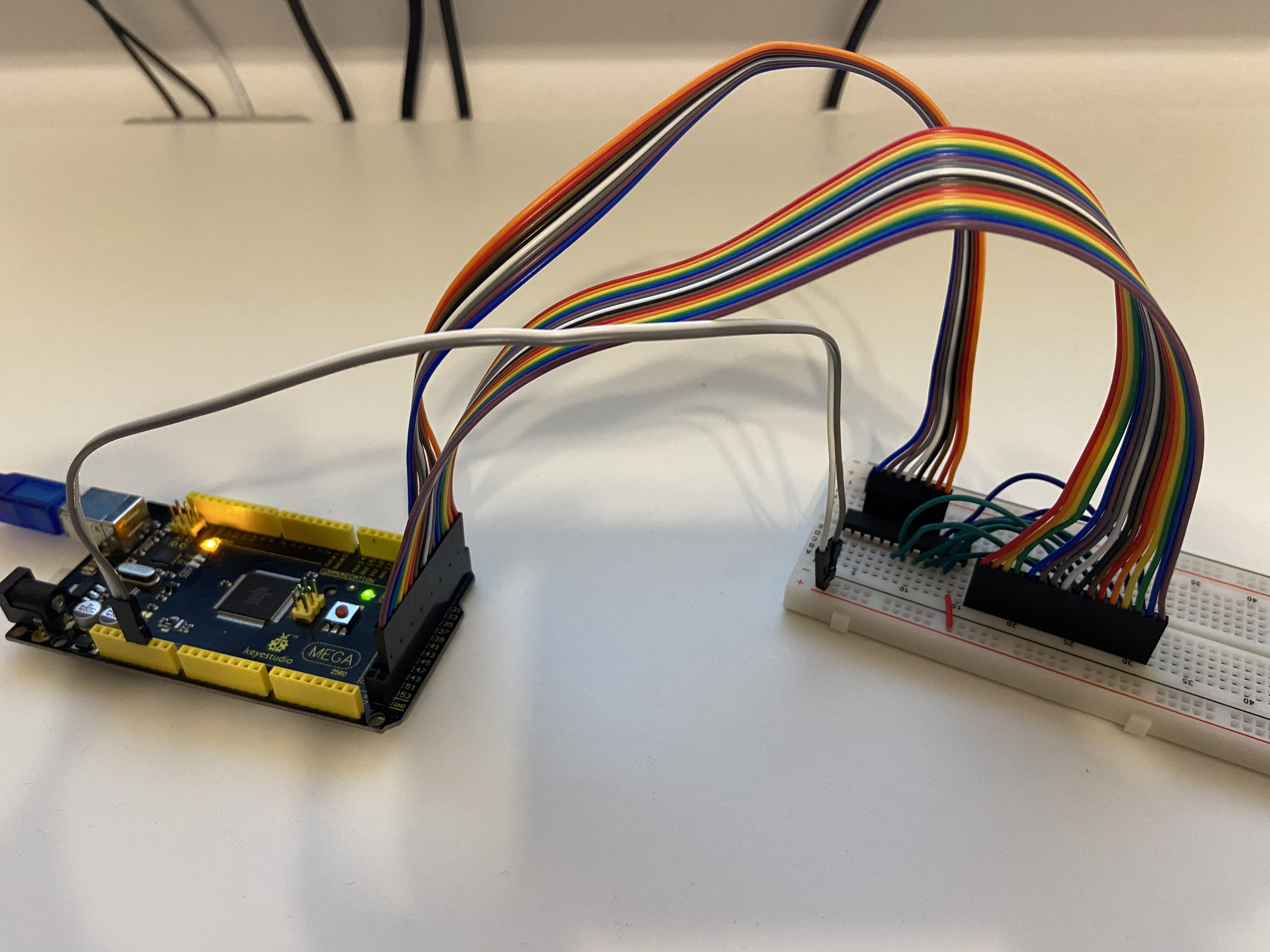
You can see the PLD plugged into breadboard with the wires connected to input/output pins. Pretty simple, isn't it?
This is where the fun started. I ran my program:
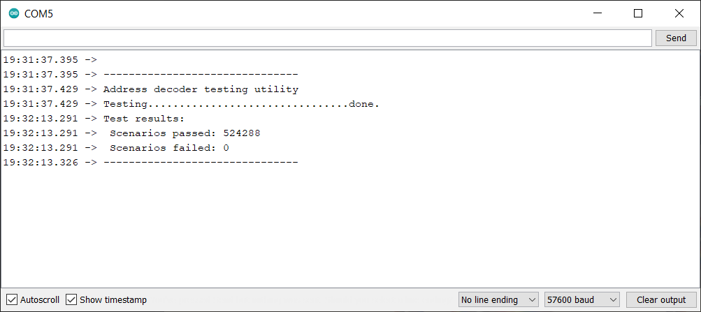
Oh, I thought, it must have failed. I mean seriously, it couldn't have worked the first time around, right? Right?
Took me about an hour of various negative tests to come to final conclusion: the code just worked. Yes, the first time around. Yes, the PLD was correctly programmed. Yes, the first time around :)
I guess miracles do happen!
Discussions
Become a Hackaday.io Member
Create an account to leave a comment. Already have an account? Log In.