 Charlie Smith
This has been an ongoing project for over a year before being added here, so in addition to the overall design here, I will merge everything done so far into a the first log rather than trying to separate everything as it happened.
Several years ago, there was a number of very interesting tutorial on making an 8-bit computer in breadboards produced by Ben Eater. While I had done some electronics before (mostly for school), this was my first large scale project which. With the help of these tutorials I was able to build it myself:
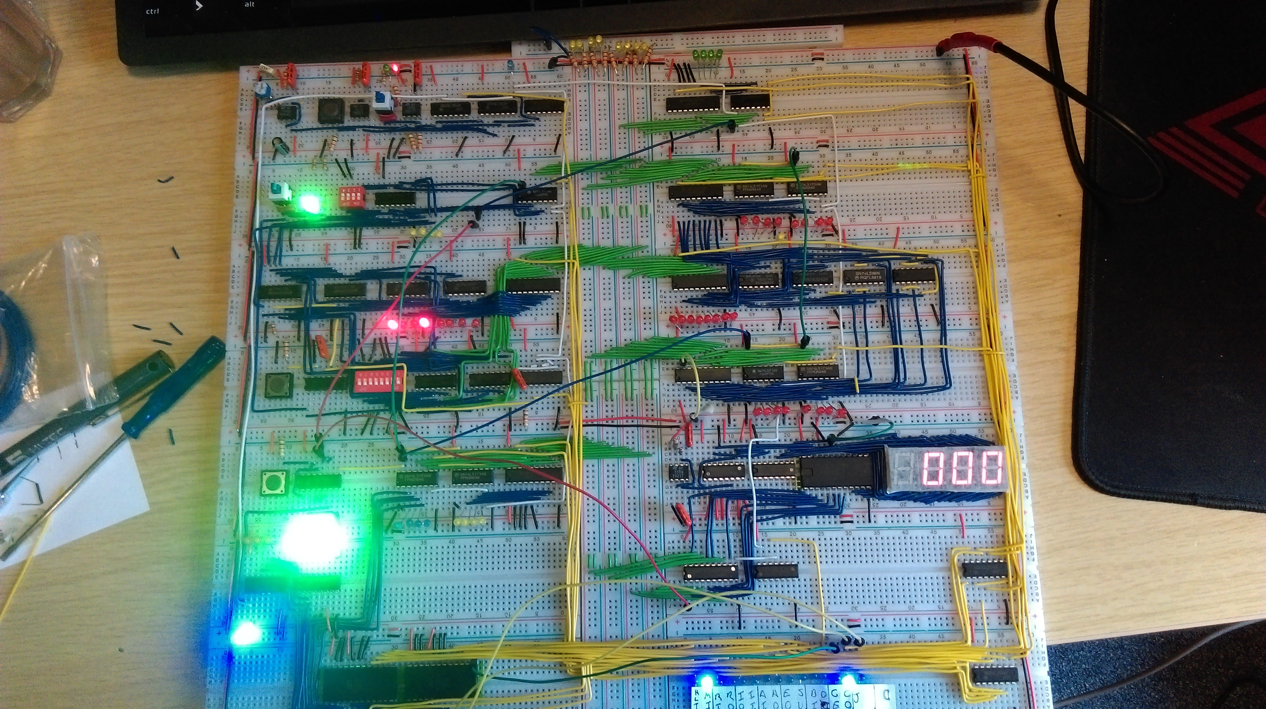
This computer uses 74LSxx chips for almost everything, with the exception being 555 timers for clocks, and AT28C16 EEPROMs as configurable logic to prevent some parts getting way to large. While I could get it running, it only has 16 bytes of memory, and to program it you need to set each byte individually. This firstly isn't much memory to do anything in, and secondly doesn't scale well even with an expanded memory. It also wasn't exactly my project as I had just followed a tutorial. As such I decided to build my own better, bigger, and as it turns out very troublesome version. There where several design considerations I set as rules:
- The computer would use a 16-bit word
- The computer would mostly use 74LSxx chips
- I was allowed to use more complicated chips for RAM and again use EEPROMs for configurable logic where size would get out of hand
- Use PCBs rather than breadboards to make it a bit more permanent
- Be able to store a program in EEPROM chips rather than enter it manually
- Have as much RAM as is feasible for the word size (64K words)
- Be able to add new modules for future expansion
- Keep the same rough design as the Ben Eater computer
- LEDs, lots of LEDs
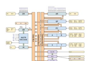
The computer has this overall design:
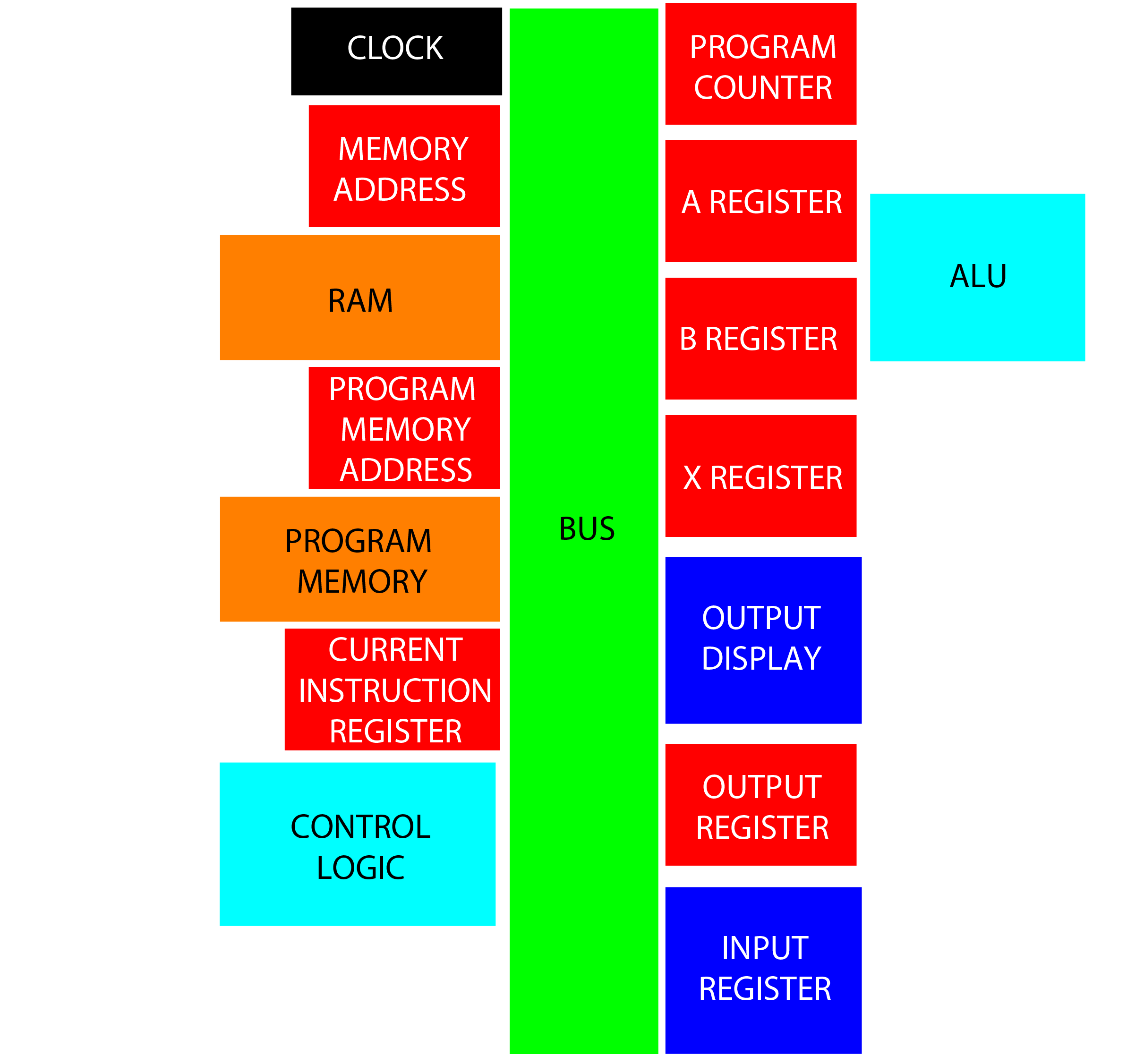
- Clock: Synchronize the computer with both variable frequency free run and single step modes
- Program Counter (PC): Stores the address of the current instruction
- Memory Address (MAR): Stores the address of the value to fetch from RAM
- RAM: Stores all variable data during runtime
- A Register: Stores the current working value, and result from ALU
- B Register: Stores secondary value for ALU to perform calculation
- ALU: Performs some calculations using A and B registers, must at least to addition and subtraction
- X Register: Index register which can be incremented using a single instruction without affecting A register
- Program Memory Address (PMAR): Stores the address of the value to fetch from program memory
- Program Memory: Stores the program in EEPROM
- Output Register: Stores a value to be displayed
- Output Display: Displays 16-bit value as decimal
- Input Register: Allows user input of some form, should allow for both wait for input and read current value
- Current Instruction Register (IR): Stores the current instruction being used, must be 16 bits plus the opcode size (likely just use 2 word register)
- Control Logic: Decodes what is in IR to generate control signals for the rest of the computer, also handles flags and reset
ToDo: Write about choice of RAM and EEPROM, and some other design stuff (either here of in log)
With everything designed the full computer looks like this:
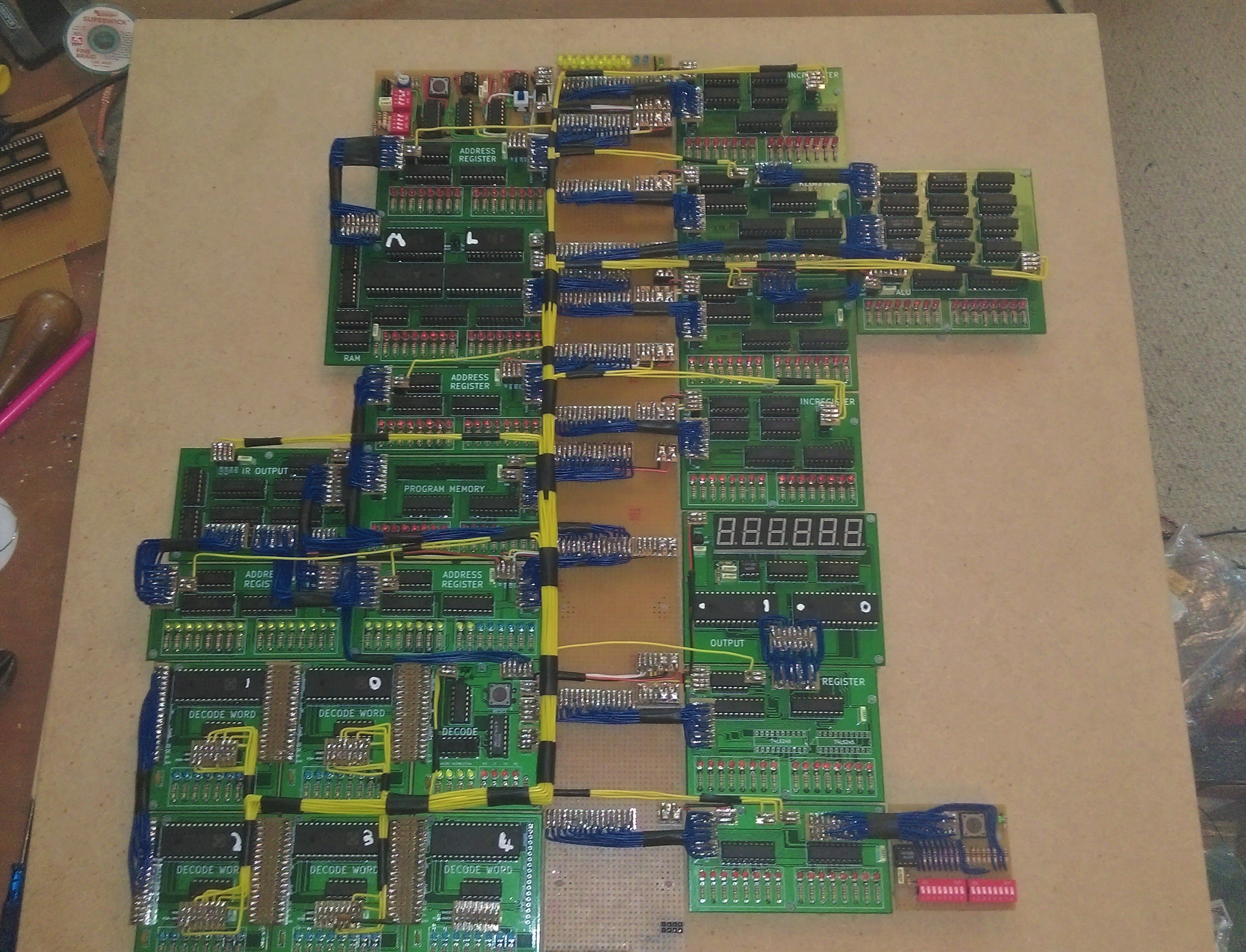
Unfortunately the computer isn't fully functioning. All separate modules have been tested, however the complete thing does not operate correctly. There are several problems to solve:
- Clock does not have a fast enough slew rate to function with 74LSxx logic.
- This has temporarily been replaced with the clock from the original Ben Eater computer.
- Control logic EEPROM 4 outputs high on each bit, regardless of being programed (and checked) to be all 0x00. This isn't really a problem as it is an extension to the control word and non of the bits are being used.
- Rough control signals are being generated. This causes modules to not perform correctly, mostly reading values whenever another register reads. THIS IS THE MAIN PROBLEM TO DEAL WITH
- It seems adding a 10nF capacitor to ground on the control lines somewhat helps with some modules. This has not been tested for all affected control lines,...
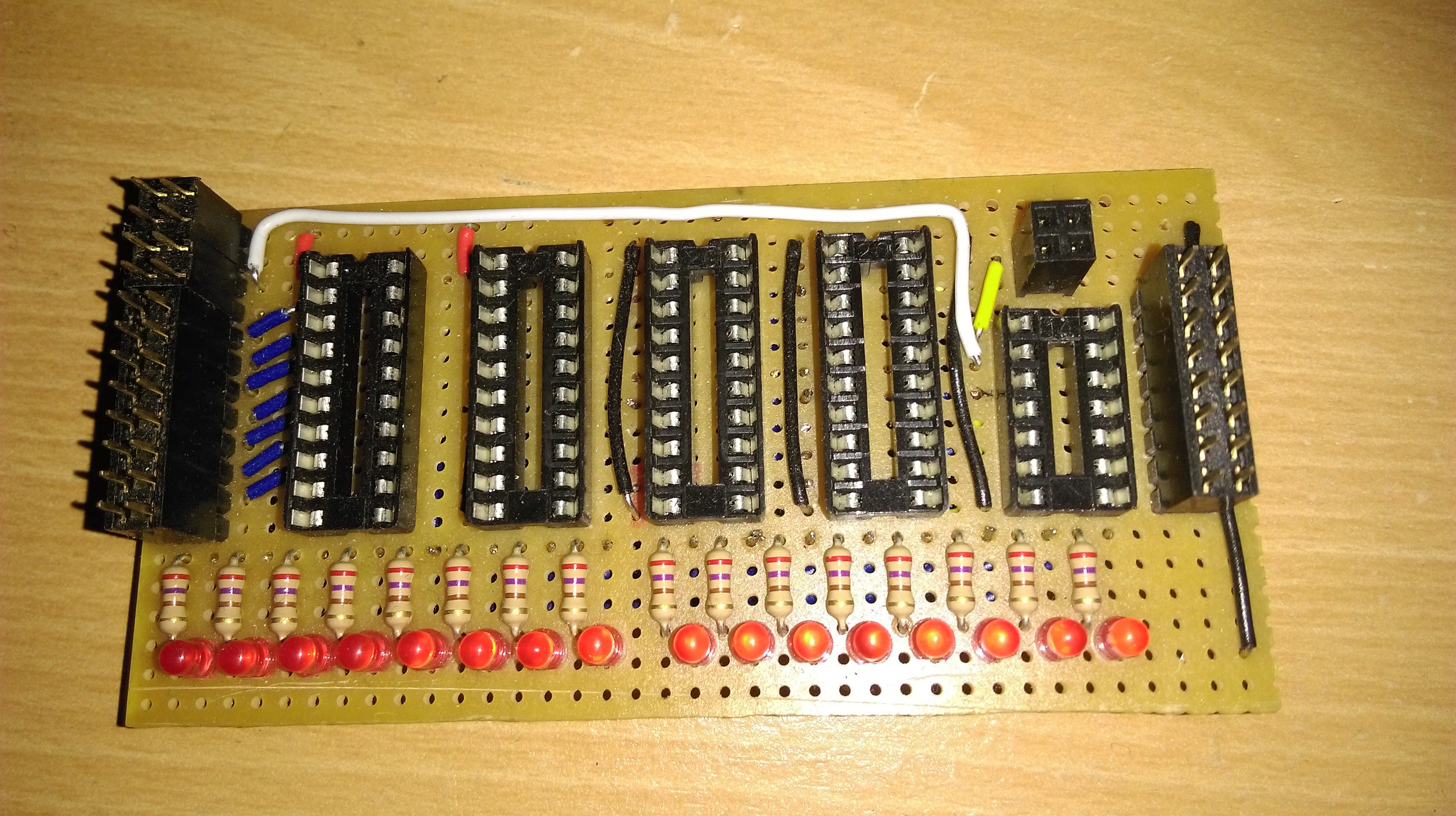
 This is clearly a mess (and I'm surprised that I did so much of it before giving up). It was very tedious to build, prone to error, and extremely difficult to debug and fix. The main issue being that with 16 data lines (needing a connection from the bus connection to the flip-flops, from the flip flops to the LEDs, from the flip-flops to the bus driver, and finally from the bus driver to the bus connection), and the remaining signal and power wired: over 70 individual wires are needed, and this is one of the simpler modules. As such I gave up building the entire system in this way. There are still some parts I still decided to used strip-board. Most notably the bus as it is so large, and mostly just a lot of parallel strips (i.e. exactly what a strip-board is). As an alternative fabrication method I had an experiment with making my own PCBs. For this I tested an EEPROM programmer for the AT28C16 ICs. For this I set up a headed container of Sodium Persulfate (as its apparently cleaner and more controllable than ferric chloride) with an air bubbler. To place a mask for the copper to keep, I experimented with laser printing onto paper, placing the paper toner side down onto copper clad board, heating the lot with an iron, and then removing the paper after soaking it in water for some time (there are definitely better tutorials out there that explain this). After a couple of attempts at transferring the mask I ended up with one I was happy with, etched and added the components:
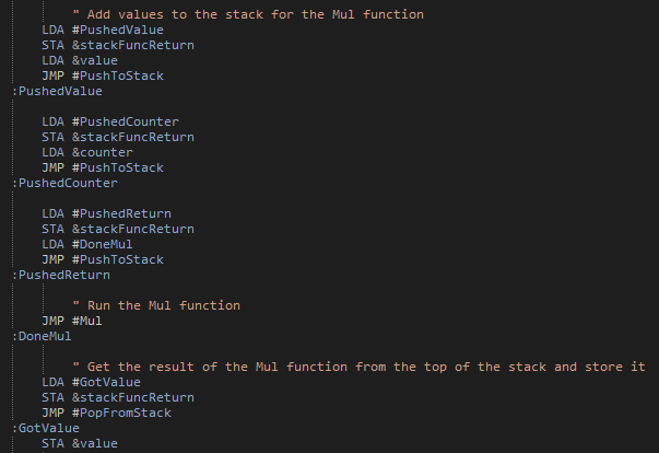
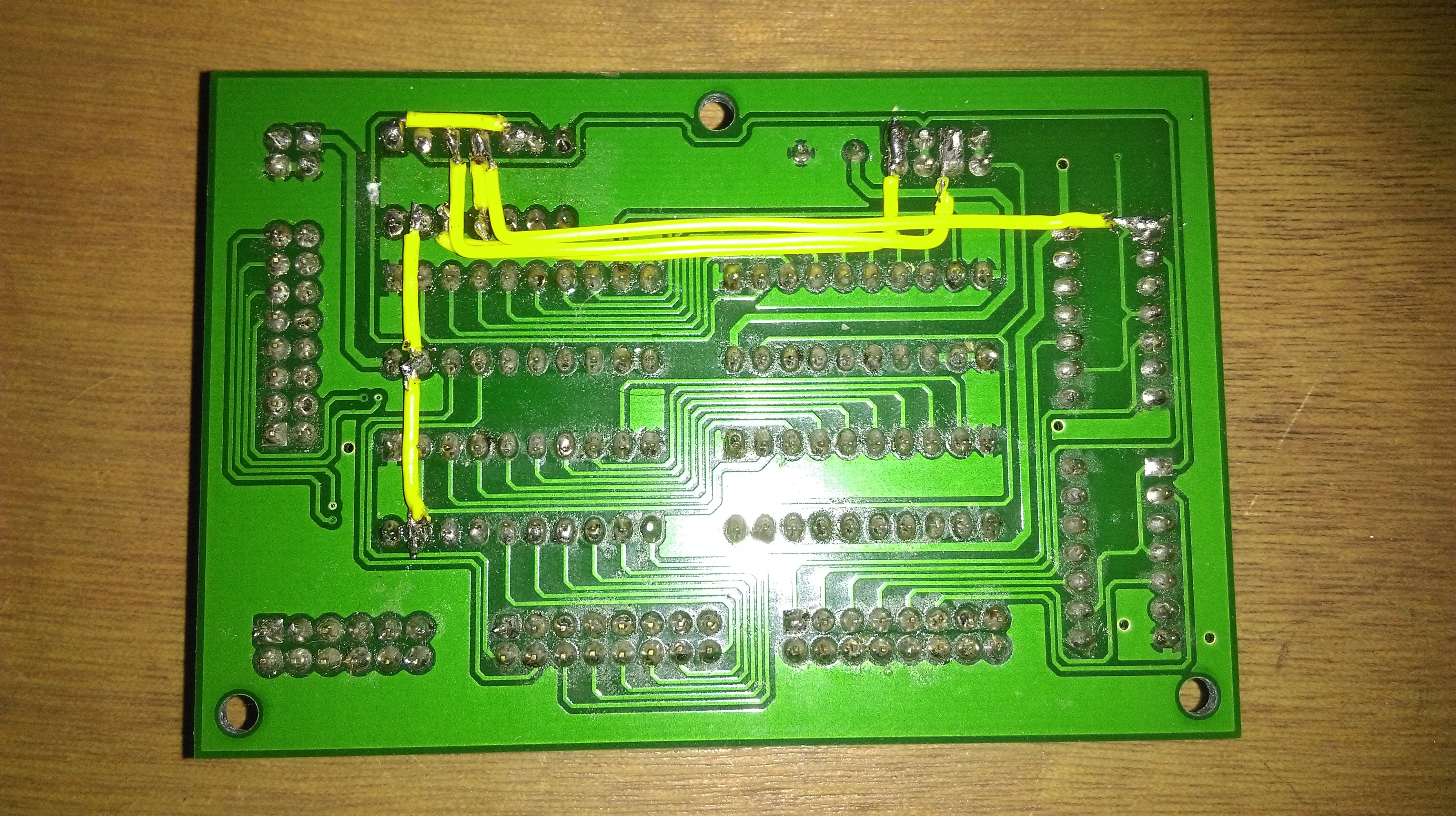
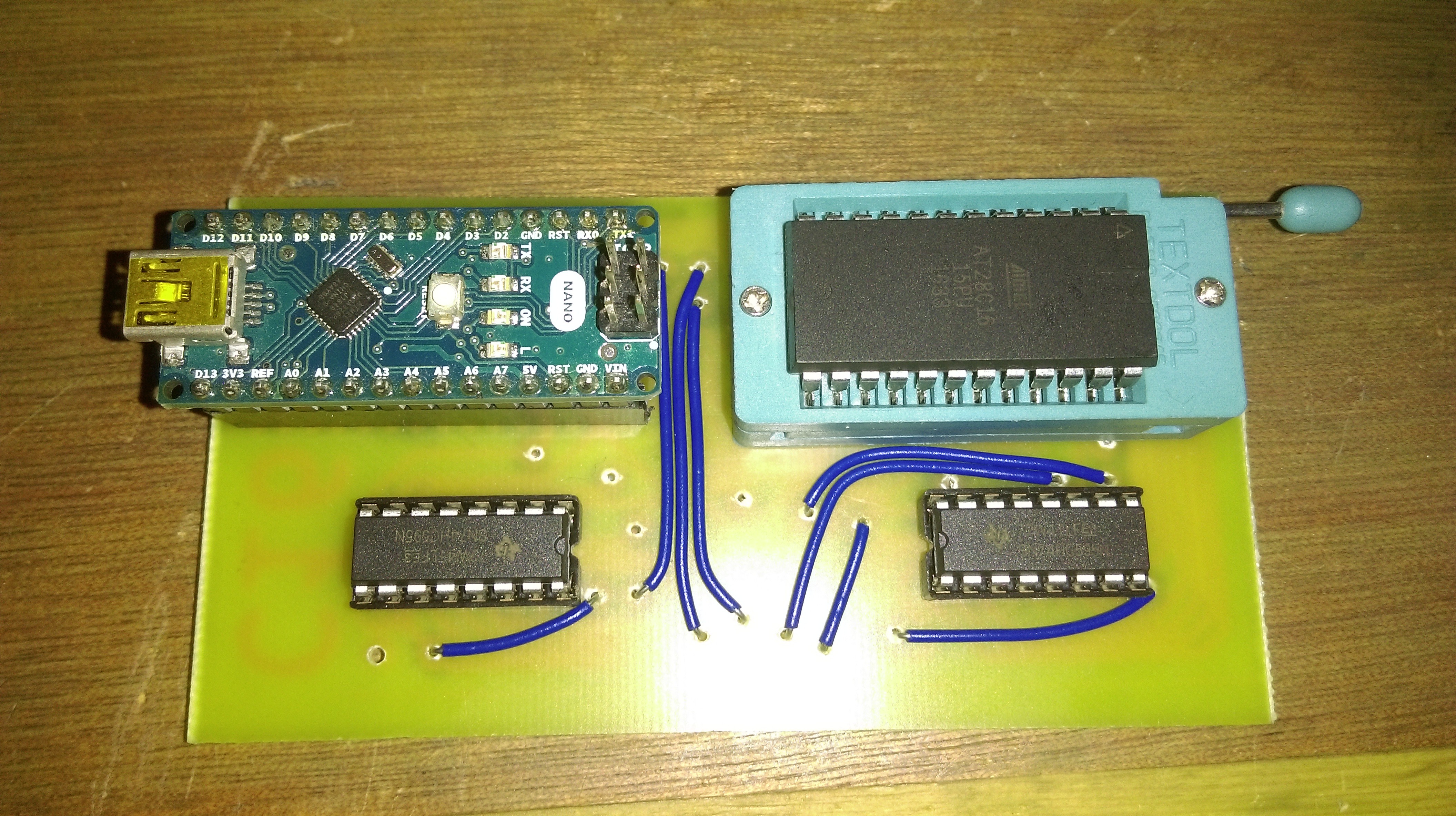 This needed a few extra wires as it is a single sided board (double sided like this sounds difficult), but this needs far fewer than on the strip-board. The other side:
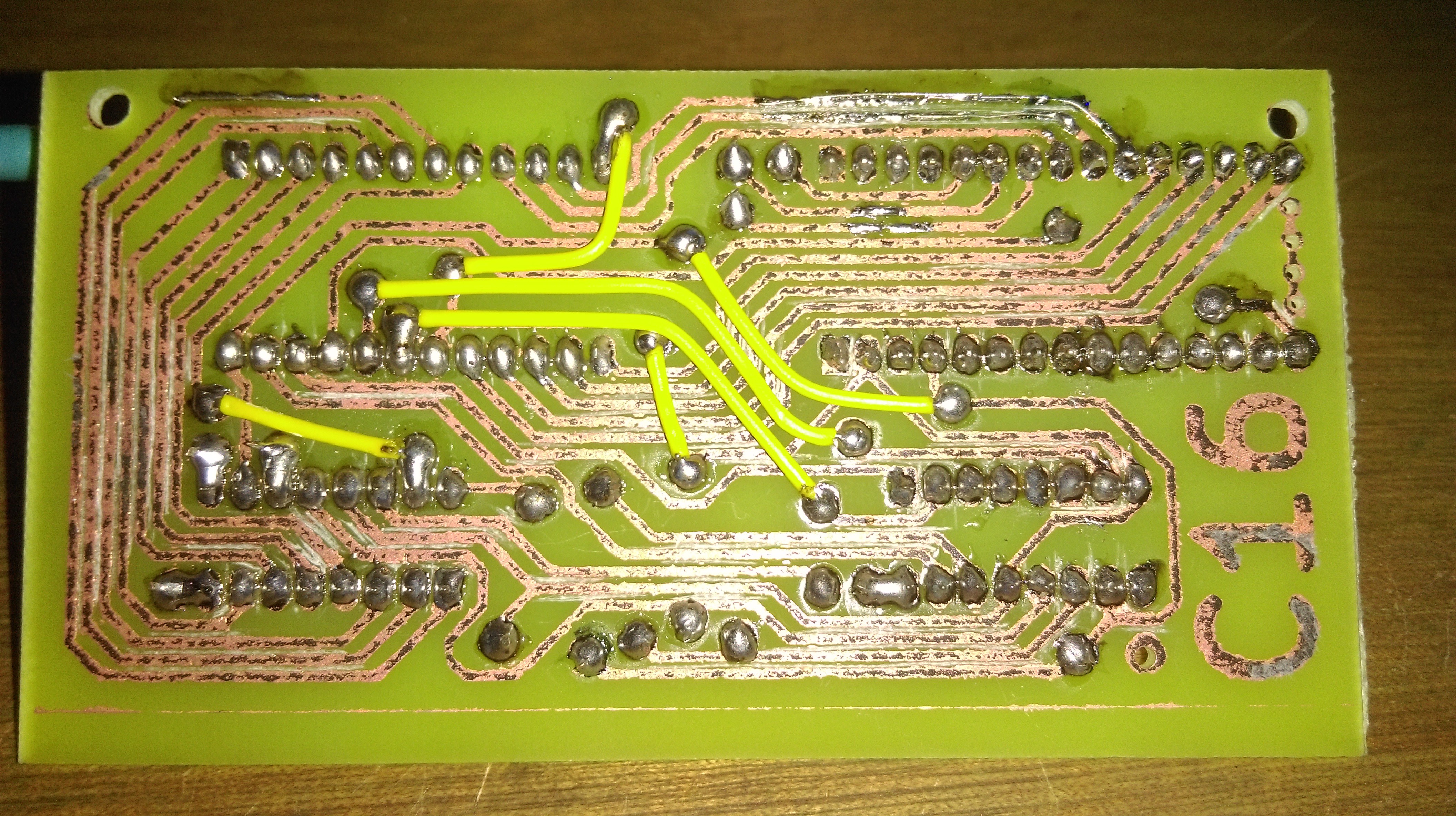 Amazingly this worked with only a few traces needing to be fixed (some extra solder on traces at the top of the picture). There were a few issues with the process of making this. Firstly transferring the mask wasn't very reliable, perhaps I need to consider printing on thinner paper to stop the toner being pulled off when the paper is removed. Secondly, etching was rather inconsistent with the bubbler I used. The bubbler only really did anything directly above it, this can probably be fixed by using one that bubbles in a line, rather than from a point. Finally, and most importantly, the board stopped working shortly after it was made. This is likely due to damage to one of the traces from the lack of solder mask. Overall the process was somewhat successful, but probably a bit too unpredictable for what I want. What's more, I then discovered


 2-Zons
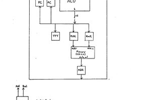
 Dave Collins
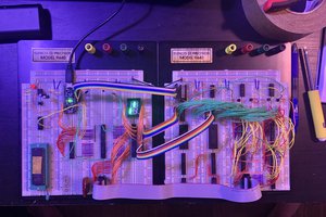
 Tim Ryan
Thoughts and suggestions - no guarantees ;-)
"Clock does not have a fast enough slew rate" - use a schmitt trigger buffer? Especially as you mention "using a Resistor/capacitor" to decouple".
"Control logic EEPROM 4 outputs high on each bit" - sounds like somewhere you have parallel wired another output. If you disconnect the EEPROM are the lines still high (enough to llight a LED)?
"Rough control signals ... modules to not perform correctly" - You may have race conditions, ie some signal needs to arrive simultaneously with another, but one of them is transient.
"Adding a 10nF capacitor to controlines ... somewhat helps" - reinforces my racecondition suspicion. It would slow down the signal. It also stresses the chips, as they have to supply/sink lots of current at the transition (no resistor to limit current).
"LEDs are far too bright" - have you measured voltage? They may pull down your logic high to a few volts - still enough to be a high ... some of the time. I'd buffer them (ie use a on lines where the fanout is more than 1, or at least on the bus (I have on my project)