Close
0%
0%

Refrigerator Magnet Clock

A clock that uses children's magnetic alphabet numbers to display the time.

Similar projects worth following
I've always been fascinated by unusual clocks. This is one of my latest creations that uses refrigerator alphabet numbers to display the time.

The numbers are placed on a piece of thin white Plexiglas that has thin sheet metal laminated to the back. There are small magnets in each of the numbers that cause the number to cling to the sheet metal when they are not being moved.

The numbers are moved using CoreXY mechanism that moves a carriage behind a number, it then engages two magnets which attract the magnets on the number and allows the number to follow the carriage movement. Once at it's destination the carriage magnets are disengaged and the number will stay in place because of the thin sheet metal backing the Plexiglas.

Here is the clock in action.

and here is the what is happening behind the clock
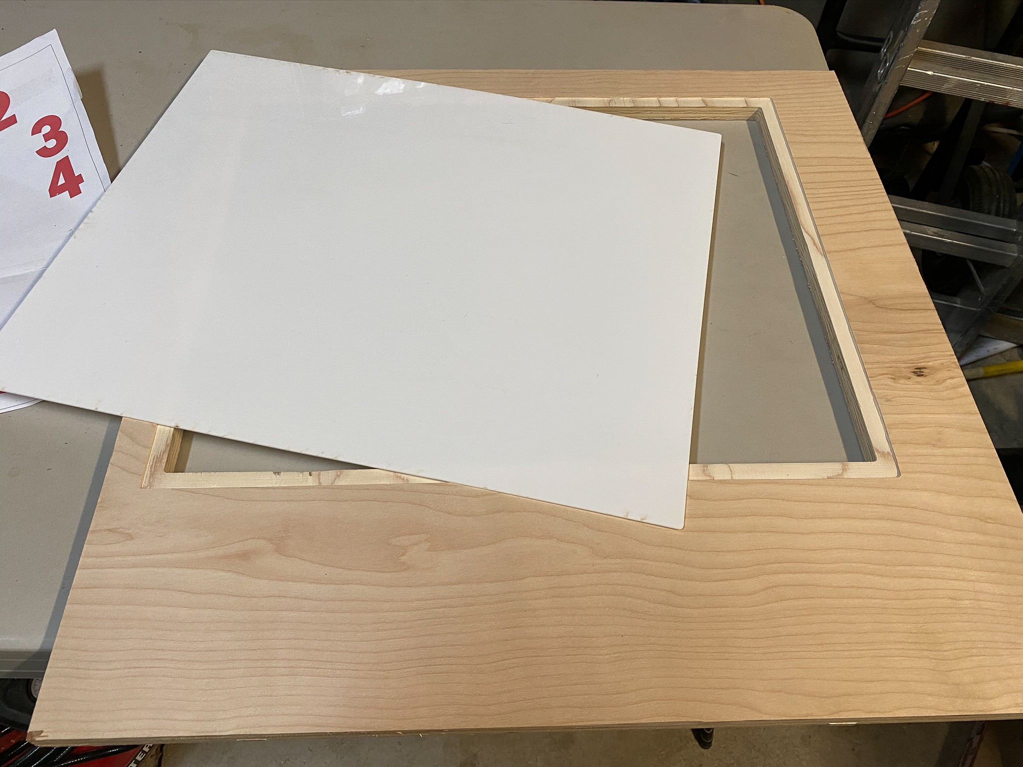
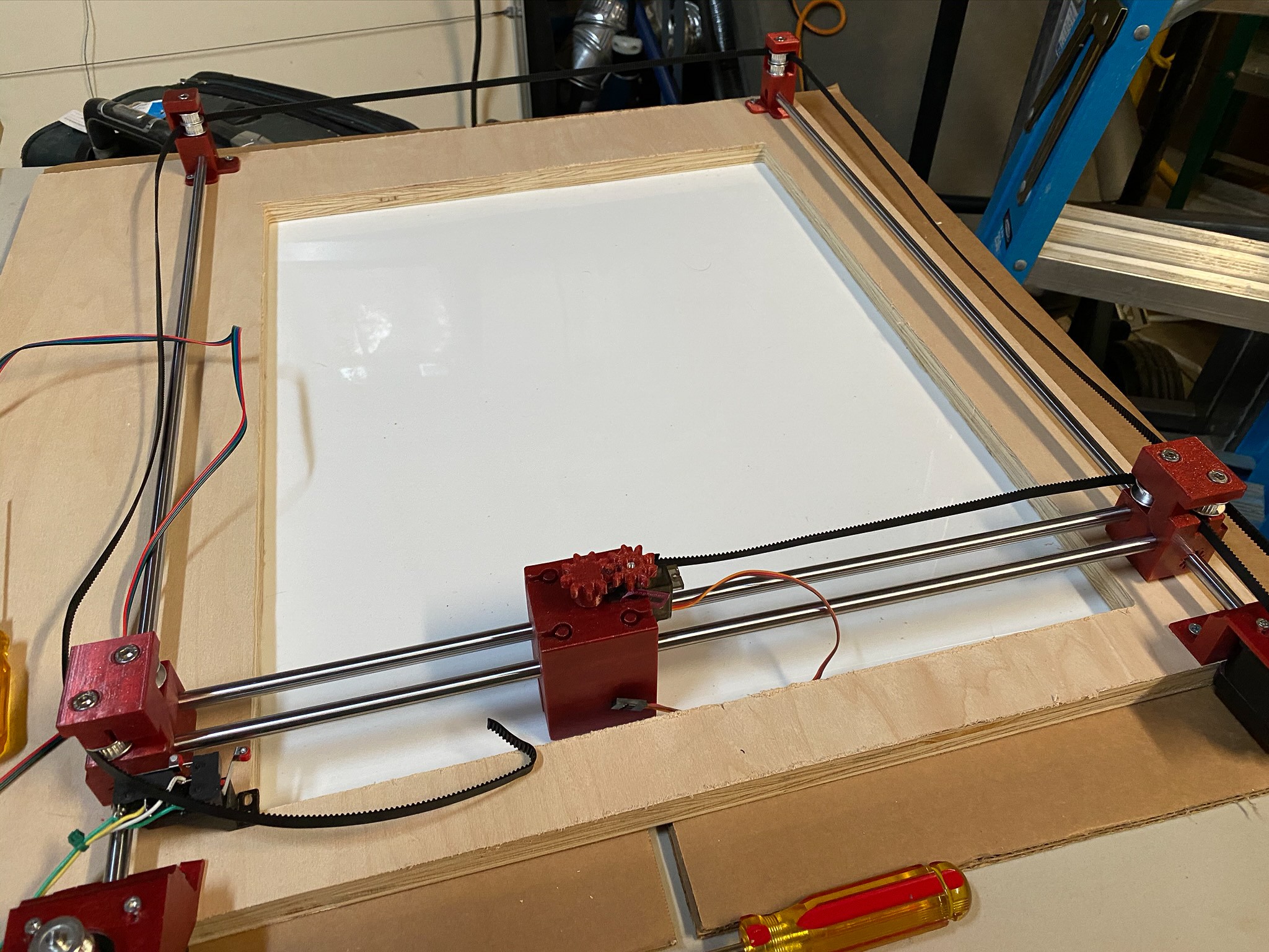
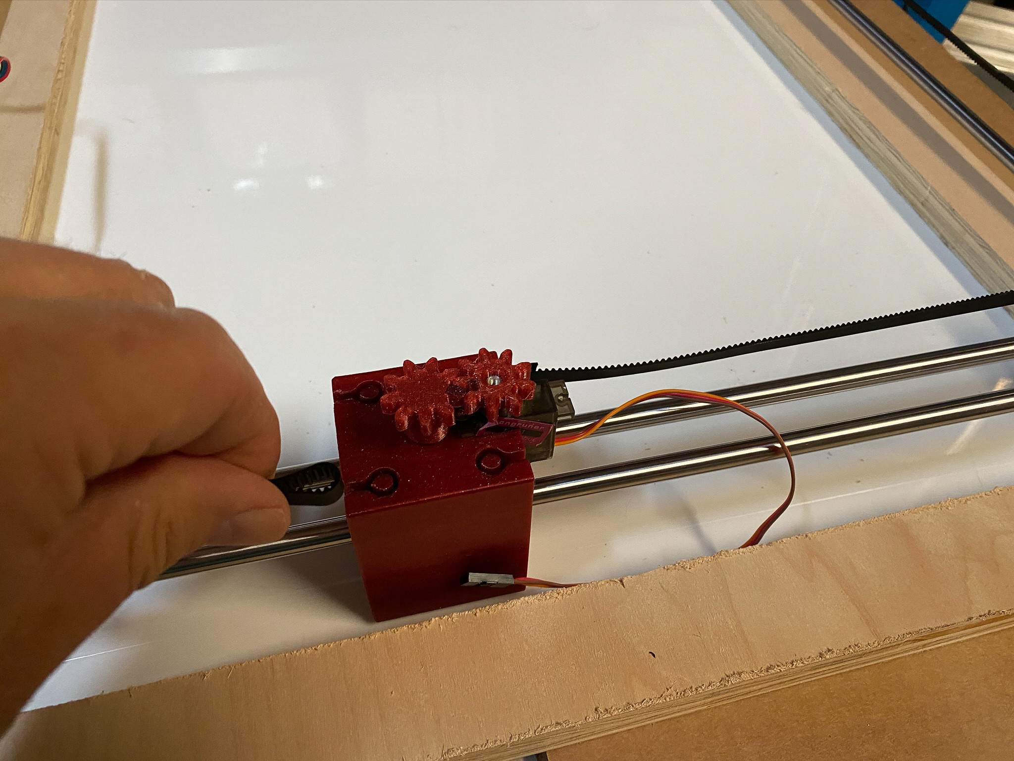
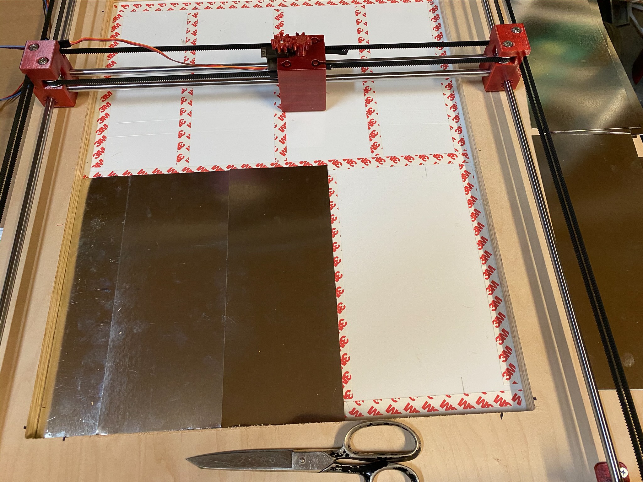
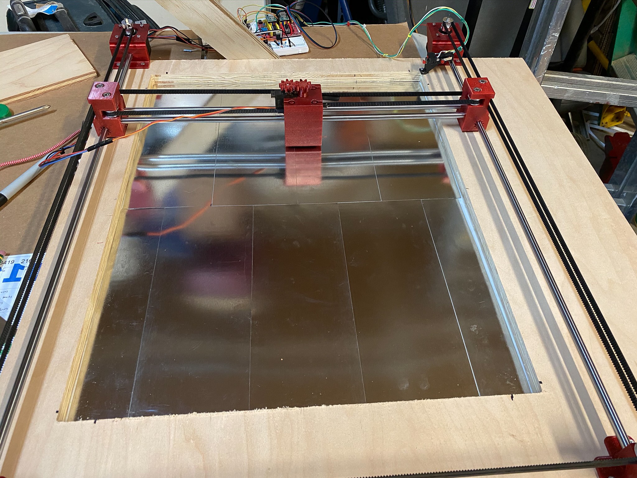
CoreXY Mechanism

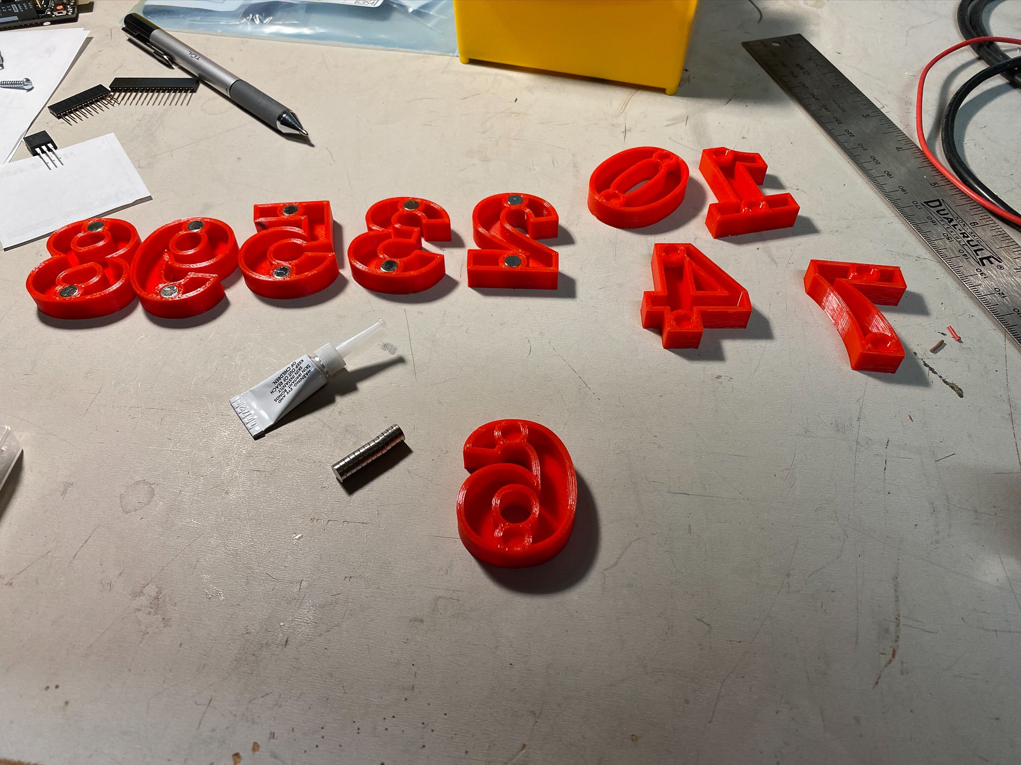
The magnetic numbers are moved using a CoreXY style mechanism on the back of the clock.

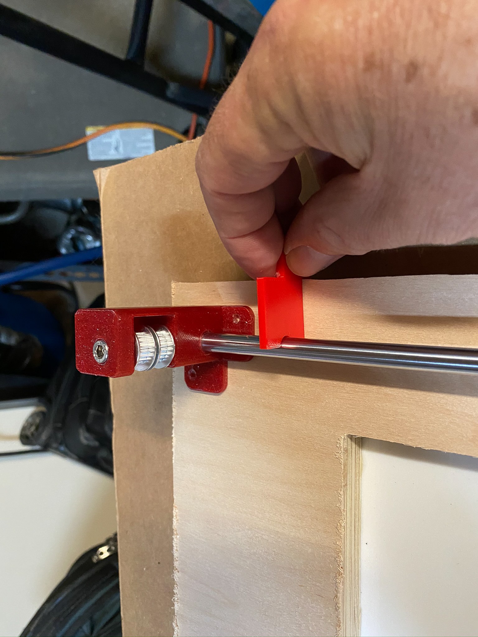
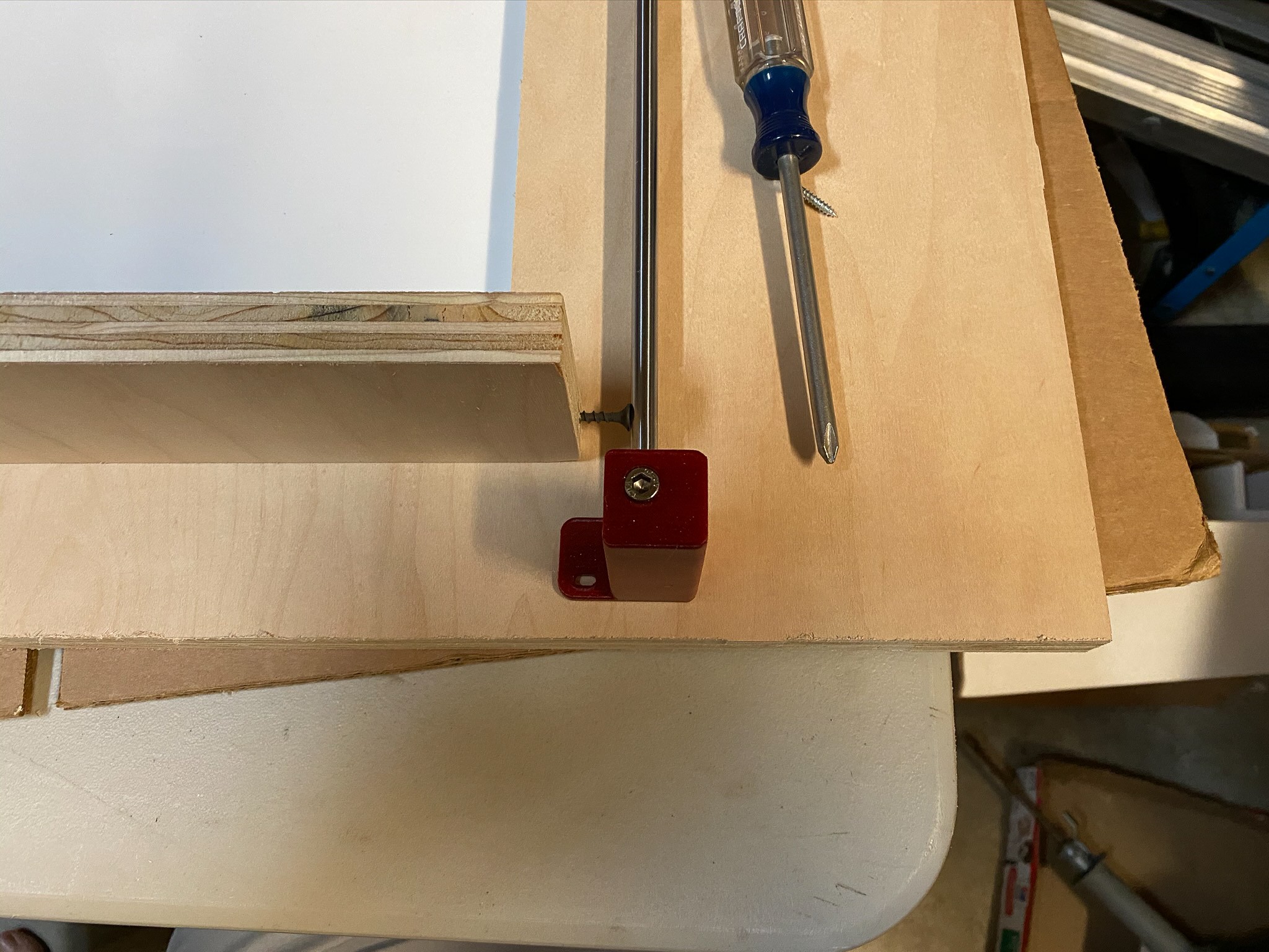
I designed and 3d printed all of the plastic parts and off-the-shelf 8mm rods and GT2 gears. The two stepper motors are Nema 17 1.5A steppers.

Electronics

The original design used an Arduino Uno controller, however during design I determined that I needed a faster processor and switched an Arduino compatible SAMD21 based controller board (RobotDyn SamD21-m0-mini). The original reason for going to a faster processor turns out was not needed, so I could probably have gone back to the Uno but just didn't bother. 

The Arduino controller is connected to a KingPrint CNC Shield using A4988 Motor Drivers to drive the stepper motors and an Adafruit PCF8523 Real Time Clock to keep time.

Source Code

All source code is available on GitHub

https://hackaday.io/project/174246-refrigerator-magnet-clock

Standard Tesselated Geometry - 112.78 kB - 08/09/2020 at 23:28

Download

Standard Tesselated Geometry - 89.54 kB - 08/09/2020 at 23:28

Download

Standard Tesselated Geometry - 111.41 kB - 08/09/2020 at 23:28

Download

Standard Tesselated Geometry - 85.63 kB - 08/09/2020 at 23:28

Download

Standard Tesselated Geometry - 64.54 kB - 08/09/2020 at 23:28

Download

View all 21 files

  • 1 × RobotDyn SAMD21 M0-Mini Arduino compatible SAM based microcontroller
  • 1 × Adafruit PCF8523 RTC
  • 1 × Miscellaneous Hardware 5mm bolts, wood screws
  • 1 × 1/16" thick white Plexiglas, 21"x19"
  • 1 × 36ga sheet metal, 20"x18"

View all 20 components

View project log

  • 1
    Details from the Build Process

    This is not the complete build instructions, perhaps I will add that in the future. This is more to show some of the details of the project.

    The plywood xwas cut using a CNC router to make a 1/16" deep pocket for the Plexiglas. The CNC makes a rounded corner (1/8" when using a 1/4" bit). So I cut the Plexiglas on a laser cutter to get a nice fit.

    When mounting the CoreXY components onto the plywood I needed to make sure the guide rods where parallel. So I 3D printed a gauge to make sure the first rod was parallel to the edge of the plywood.

    For the 2nd rod I took a scrap of plywood and put a screw into it so I could make precise spacing between the 1st and 2nd rods and to make sure they were parallel.

    Next came the timing belts.

    I had difficulty sourcing a large sheet of 36ga sheet metal so I used a bunch of 10" x 4" pieces which I attached with 3M double sided tape.

    The numbers are all 3d printed and I used Super Glue to attach the 6mmX3mm magnets

View all instructions

Enjoy this project?

Share

Discussions

hadprojects wrote 08/28/2020 at 05:28 point

Has anyone considered how this clock can display 11:11 ? ? ?  There are only three 1's.

what does the firmware do?  My guess is that it displays 11:10 then 11:1 then 11:12.

Perhaps it will steal a 1 and display 11:10 then 1:11 of 1_:11   interesting right?

This is a great example of why I never test my own code.    I can't see the minute detail that is glaring to others.

All in All  I wish I had some kids to give this clock to...

If I were a kid I would change the numbers so that only I know how to decode the real time...  reverse the digits would be fun...    I would have the numbers placed in random positions and use any color for the digit...   You could use cute icons instead of number.  You would have to remember which icon represents the number...   Yes I was that kid who always thinks outside the box.   At 72 I am still that kid.

  Are you sure? yes | no

Craig Colvin wrote 09/03/2020 at 19:45 point

There are four ones, it was just that my kitten had taken one of them before I took the photo an I didn't notice until people pointed it out to me. :)

  Are you sure? yes | no

jagulin wrote 08/14/2020 at 05:56 point

I didn't see your crossposts on Reddit first. This one seems to have most comments. Saves me from repeating some ideas already there... 
https://www.reddit.com/r/arduino/comments/i84g4d/refrigerator_magnet_clock/

Don't get me wrong, this project is already super cool for the idea and simple execution. Adding ideas to this project probably won't make it more cool. I'll drop them here anyway.

I suppose watching the numbers move is the most rewarding part, and the empty transports are the least. I didn't quite understand the layout of the predefined positions, but read it was based on smallest area and no collisions. In most cases the wanted number is next to the drop off, so that's great. Instead of hard coded storage positions, using memory to keep track of numbers not in use would be fun and allow for more dynamics. You could then also introduce more flexibility, so a number can be used for hour or minute, instead of having dedicated ones. That opens for reusing the 0 at the "09 -> 10" switch. This adds to the fun, but of course also makes the code more complicated.

To make the time change as quickly as possible, I'd consider "cache positions". When you know that you're about to change more than one number, prepare them by moving closer to center ahead of time. Moving numbers around for no reason is fun (apart from noise)  so preparation adds to the visuals and then makes the actual time change faster. 

I also thought about having room for two numbers on the carriage. Then getting the new number first and moving the old number away while pushing the new in. Unfortunately it only works in the center. Drop off at a cache position before picking up next number, then "save the cache" later. Ultimately, you can have more than one clock positions and prepare next clock face in position, then dismantle the old clock face. As with old screen savers, moving the clock face around is not only adding life, it has the bonus effect of preventing burn-in to the screen. :)

This kind of preparation should make the switch faster, but if there's any chance of needing to make 2 minute jumps, like 9:59 -> 10:01, start with hour and pick the suitable minute digit when you know how long it took. If you on the other hand have plenty of time, sync movement to indicate ticks for seconds or 10-second intervals. 

  Are you sure? yes | no

Craig Colvin wrote 09/03/2020 at 19:52 point

Thanks for the comments.

Randomizing the digit home locations is trivial, each digit has an array of 4 waypoints that tell how it moves from it's home position to the clock position. So just changing those waypoints would allow one to put the numbers wherever they want to. 

As for not dedicated numbers that is interesting. I still have to have the same number of digits, but perhaps it could randomize which one it grabs. I may play with that. 

I spent a lot of time during the design trying to think about a dual carriage and caching numbers close to their clock position. It got complicated fast, so I decided to go with the easier version first and can always revisit the caching idea. 

Some good ideas here. Thanks again for the comments.

  Are you sure? yes | no

Martin Lorenzo wrote 08/13/2020 at 11:56 point

Hey, I loved the projects, it's really awesome! It could be used in daily life if it was a little bit more silent.. Any idea how to reduce the noise? 

  Are you sure? yes | no

Darrin B wrote 08/13/2020 at 14:59 point

Sine-cosine drive for the steppers. A pair of power op-amps is all you need to try it out.

  Are you sure? yes | no

Craig Colvin wrote 08/13/2020 at 16:51 point

I ended up slowing down the carriage movement because it was losing numbers during horizontal movements. The slower movement is noisier. I have a couple of solutions I’m working on, silicon spray on the front surface and a strong electromagnetic on the carriage in place of the permanent magnets I’m currently using. Then speeding it back up.

The other Improvement will come from increasing the stepper motor drive voltage from 12v to 36v

  Are you sure? yes | no

ekaggrat singh kalsi wrote 08/13/2020 at 01:40 point

really cool project! I wanted to do something similar after building 3 writing clocks but never did as i couldn't figure out a way to make the system know where the numbers are on power up! 

  Are you sure? yes | no

Craig Colvin wrote 08/13/2020 at 03:24 point

I have an initialization routine have have the computer place them in their appropriate home location. It moves the carriage to the middle of the board, I then place the number approximately in the middle, the magnets get it perfectly aligned and then the computer puts it away and comes back to the middle for the next one. 

That only has to be done one time. Once they are in their home location the computer knows the coordinates and can retrieve them. Even when you power cycle the computer the numbers haven't moved so the computer knows the hardwired coordinates.

BTW I'm huge fan of your work and have been following your projects for a while now. Super creative stuff. 

  Are you sure? yes | no

ekaggrat singh kalsi wrote 08/13/2020 at 08:27 point

that is a really clever approach. and 

thanks for liking my work :)

  Are you sure? yes | no

Gerben wrote 08/12/2020 at 11:15 point

Very cool.

I was thinking, that if you added a hall-effect sensor to the X-Y carriage thingy, you should be able to detect where all the pieces are, after the power goes out.

  Are you sure? yes | no

Craig Colvin wrote 08/12/2020 at 18:15 point

Ideally the numbers stay in place. The numbers around the edge are at fixed knowncoordinates. The only thing the software needs to know at power up is what numbers are being used to display the time so they can be put back in their home position. 

Again the positions are known so a hall-effect sensor wouldn't help there, what is really needed is a way to identify what the number are. Maybe some very short-range RFID? 

For now on power-up the software prompts the user for the currently displayed time and then stores those digits in their correct home position before displaying the new time. 

  Are you sure? yes | no

Gerben wrote 08/13/2020 at 15:01 point

Thank you for your explanation.

You could use the hall-effect sensor to see which outer numbers are **missing** from their home position.

You can then check the center and move the clock digits back to their home position.

In the case that one digit is missing from the middle (power removed during transit), you'd have the scan the whole area (or at least the path from the digits center position to its home position), to see where it was at. Oh, wait. If that's the case you'd know the digit is where the carriage was during boot-up, so you could use that.

Your solutions sounds a lot simpler. I tend to want to over complicate things (-;

  Are you sure? yes | no

Craig Colvin wrote 08/13/2020 at 16:46 point

using the Hall effect sensor to detect holes in the home numbers is brilliant and eliminates the need for user input on start up. I’ll experiment with that.

  Are you sure? yes | no

jagulin wrote 08/14/2020 at 02:44 point

Beautiful project! I can't resist sharing extension ideas, though I'm sure you don't need them. :)

Instead of RFID, is it possible to reposition the magnet slots into a unique configuration per number? Depending on precision of Hall sensor and XY positioning, identification then might be as easy as "how far apart are the top & bottom magnets?"  Would that, or adding a third magnet to some, interfere with the grabbing and moving? 

Are you able to read out the XY  position at boot, or you need to reset into known state (homing) to establish coordinate system? Another half-stupid idea is to park the carriage at defined positions, like X = hour, Y = min. If booting in a known position, assume that's the time. The stupid part is that it introduce more fail states, e.g. assuming the wrong time and getting numbers misaligned.

I suppose it would be easier and cheaper to just use some non-volatile memory to store "current time" and position. How do you keep track of  RTC currently?
https://forum.arduino.cc/index.php?topic=144251.0

Another benefit of hall sensor would be to sense if you dropped the number when going fast. It would require some testing to find out how the carrying magnet affects the sensor, however. Especially if you go with a variable electro magnet, which on the other hand can be turned off. 

  Are you sure? yes | no

Neduhamel wrote 08/11/2020 at 11:32 point

Great idea and very well executed. Congratulation.

Could be very cool to make a IoT message board with this !

  Are you sure? yes | no

ericcherry wrote 08/10/2020 at 22:38 point

Fantastic! Love the idea, love the build.

  Are you sure? yes | no

Dan Maloney wrote 08/10/2020 at 22:12 point

I love this! And yet I must not build it, because the temptation to have it randomly spell out rude words would be too overwhelming.

  Are you sure? yes | no

Craig Colvin wrote 08/11/2020 at 18:55 point

I'm surprised I had never considered adding letters to the mix. What have you done to me? :-)

  Are you sure? yes | no

Dan Maloney wrote 08/12/2020 at 00:46 point

Would you kill me if I suggested building this into the door of a real fridge? Because that's what I did in the article I just wrote up featuring this project. Sorry...

  Are you sure? yes | no

Craig Colvin wrote 08/12/2020 at 01:57 point

For some reason there was no reply button on your comment about building this into the door of a real fridge.

I think that's a great idea! I was wondering how I was going to have enough room to add letters, because would need a fair amount. 

Now you really got the wheels spinning....I would replace the guide rods with linear bearings......would need electromagnets on the carriage to work through the thicker steel.....Hmmm?

  Are you sure? yes | no

jagulin wrote 08/14/2020 at 04:05 point

For a real fridge, you usually want food inside, so best is likely to hang your design on the outside of the regular door. If it's an art-installation and you don't care about the fridge usage, replace the door with thinner metal.

Spelling words is an interesting challenge. Saying only YES, NO and ALARM would be safe. Arbitrary words will never work, but you could limit to non-repeating characters. Alow mispelng and H4X0r? Or look at English statistics to find out appropriate letter frequency and set a limit to 4-5 letter words?

There's also ready-made magnetic "fridge poetry" words. I wonder if those can be moved as well. Would go well with a fortune cookie software.

  Are you sure? yes | no

Dr. Cockroach wrote 08/09/2020 at 22:15 point

Very cool way to display, that's a great idea that I might have to look into for my somewhat strange LLTP cpu project.

  Are you sure? yes | no

Similar Projects

Does this project spark your interest?

Become a member to follow this project and never miss any updates