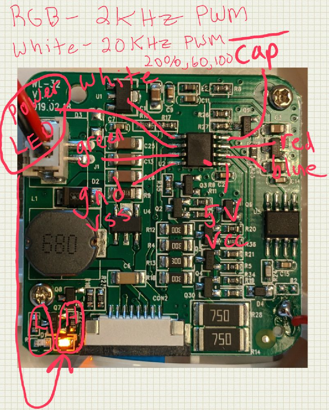
• Hack it

    Joel08/16/2020 at 06:34 0 comments

    Since all the ICs have had their markings removed, I'm not sure what the chips actually are. But, a quick check of the footprint of some 8-pin PICs verifies that I can swap the unknown chip on the PCB out for one that I can program.

    I did a parameter search for an 8 pin device with PWM and an EEPROM, since I wanted to use hardware PWM and be able to save settings. Interestingly, the PIC16F18313 was the only candidate.

    https://www.microchip.com/wwwproducts/en/PIC16F18313

    This PIC has only two PWMs, so I can't use it with all four LED drivers. I'll just power the white LED driver with this hardware PWM, and bit bang the remaining three 2 kHz RGB drivers.

    A really nice feature of this modern PIC is the preferal pin select, which allows me to programmatically assign functions to pins. This way, I can assign the hardware PWM output to match the existing footprint. The other pins will just be GPIO, so nothing special needed there.

  • Take it apart

    Joel08/16/2020 at 06:23 0 comments

    First thing to do is take it apart.

    • Carefully remove the four screws in the base under the anti-skid rubbery circle

    Now that it's apart, probe around and figure out what the chips do and what signals exist at which pins.

    • Pin 5 of U2 has a 20 kHz PWM signal on it. As the brightness changes, it cycles through 20, 60, and 100 % duty cycle. When the LED is to be off, the pin is held low.
      • The white LED driver appears to be a switch-mode constant current design. The details of the design are not important here, since we know how to control it.
    • Pins 2, 3, and 7 have a 2 kHz PWM signal, with duty cycle correlating to the following:
      • Pin 2: Blue PWM
      • Pin 3: Red PWM
      • Pin 7: Green PWM
      • It is interesting to see that these LEDs use current limiting resistors, with PWM being used as more of a voltage source here. Again, not going to dig in to it because I know how to control it.
    • Pin 6 changes when the power LED changes. For my version, I won't be using this. In fact, I may even disable this entirely, since I'm not sure why a lamp needs an LED to indicate that it is on.
    • Pin 4 is pulled low when the shroud is touched, so is the input from the cap sense interface chip, U5. Again, the implementation doesn't matter, all we care about is the signal.
    • Pin 1 and 8 are power and gnd, respectively.

    Sometimes I find my old Galaxy Note useful!