 Paul McClay
MRRF
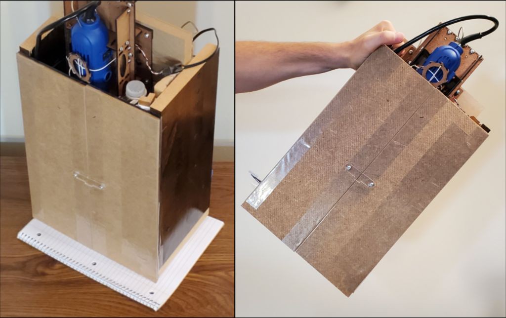
Last weekend I parked the current iteration of this project on a table at #MRRFX for a day. MRRFX being the tenth (Xth) gathering of the Midwest RepRap Festival (MRRF) "the largest gathering of 3D printer enthusiasts in the world!". There I met some really neat people, learned some stuff I didn't know I didn't know (busy day for Dunning & Kruger), and realized that I'm doing Z wronger than I thought.
I have only casual acquaintance with 3D printing and nothing of the sort to show, but teh Internetz said a few mill/router projects had crashed the show in the past without scandal. This year Joe Spanier brought his aluminum-eating Milk Cr8, and Duet3D had a colorful router running their controller(s) -- all news to me.
The trip was kind of an impulse idea decided only a few days before and prepped in haste. I wasn't at all prepared to be socially competent or retain names and contact info for many of the people who stopped for substantial conversations -- about this and about their own projects and experience too.
soft threads
Prompted by meeting Stefan Hermann of CNC Kitchen, I checked out some of his work including his 2019 review of threaded inserts for 3d prints where he measured torque-out and pull-out strength of several different types of heat-set brass insert -- including none. For "none", he drove screws into bare holes in relatively soft printed material. He confirmed expected low resistance to torque-out -- a reason why inserts exist. But, contrary to expectation, he measured pull-out strength nearly equal to the better inserts and several times better than the simplest/cheapest insert.
Most of the minimized design of this little CNC project is held together with short machine screws run edgewise into soft "hard"board -- which seems like it shouldn't work at all. The very low resistance to torque-out i.e. very great vulnerability to stripping threads out of hardboard viscerally reinforces the expectation of weakness. Stefan's finding that un-reinforced threads in relatively soft material can usefully resist pull-out even when vulnerable to easy torque-out gives somewhat better rationale than simply shrugging at the unexpected result that the method of assembling these "Minamil" designs apparently works.
A consequence of low resistance to torque-out -- i.e. ease of stripping threads -- is that while screws can be used to hold parts together, they can't be used to used to draw parts together and generate clamping force in the usual way. Most of the screws in one of these linear slides hold the clamps that hold the rods & bearings. A very early lesson in working with this design was to not use the screws to close the clamps but instead to mash the clamps directly then carefully turn the screws down to hold them. Also it becomes Very Important to take care to re-engage existing threads when removing/replacing screws in previously formed threads.
Z realization
We don't need no stinking counterweight!
but first, some history...
(or skip to last heading)
I first used one of the prototypes of the slide used for X & Y because it was handy to try. Then I used the same slide as X & Y and added a tool clamp to it because it was already done in CAD. That's the currently published design, it works, and later developments have not compellingly surpassed it, so that's ok. But it's not really a satisfactory endpoint because there's no reason for the Z axis to mimic the X+Y axes when it does a different job under different constraints. (for completeness: the zeroth Z axis was a fixed stand over the XY table)
Gravity, obviously. The counterweight arrangement got me over that hurdle and I mostly stopped thinking about it. Until recently when... I'll come back to that down the page.
Cutting forces at the tool tip act on the Z slide through a pretty long lever, which ups the ante for stiffness. The size and clearance requirements of the XY stage set a minimum footprint. There's little reason for the projected area of the Z stage to be any smaller than that. The length of a rotary tool + Z travel sets a minimum working height above the XY stage. Keeping the Z slide shorter than that does have some benefit in allowing a shorter closed storage height with the tool removed, but I don't give much weight to that advantage over allowing growth in height in trade for other benefits. I built the current (2nd) frame with (initially) unallocated space under the XY platform and extra height to protect the maximum upward extension of the currently published Z slide, then didn't feel bad about growing even taller when we get to that... So there's plenty of room for the Z slide to spread out its bearings, both horizontally and vertically, for greater stiffness. The less-minimal Z axis in recent photos and shown at MRRF grew both horizontally, to spread out the two lower bearings, and vertically, to give the upper bearing greater separation from the lower pair -- especially in the upper range of travel. It also spreads out the clamp saddles and some details of the clamp/slide interface significantly stiffen the moving assembly -- at least in my imaginary FEA -- but I don't think that was the weak spot so I don't expect much gain from that.
The last couple of iterations gained length by copypasting the slide into a tandem pair and deleting half of the (doubled) hardware:
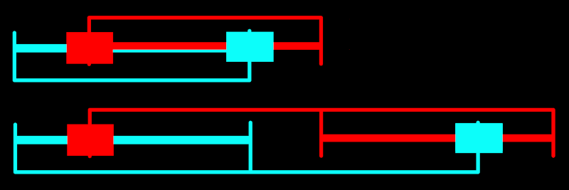
But this is unnecessarily unconventional when the only gains are lazy CAD and extending the bearing span well into diminishing returns, especially in the lower range of motion. Also the top end of the moving part is vulnerable unless protected by an even taller frame. So this could use instead a more conventional arrangement of fixed rods and moving bearings (or: all the bearings either fixed or moving).
...and some historically projected future...
If keeping with the same length rods (for simple BoM), the next iteration might look more like:

I think that's enough longitudinal bearing span to be not the weak link. When the rotary tool is not attached the top end will be lower, fixed and relatively less fragile. An obstacle has been working out how to get all of: protected leadscrew, access for backlash adjustment, best clearance of the fixed part above the work surface, and simplicity. Because motor placement constraints not illustrated. But I think that's about to cease to be a problem.
Oh yeah, I said I'd get back to gravity down here. The Z axis needs help to cancel gravity. A constant force spring (think retracting tape measure) would have been great but I couldn't find a suitable part and anything anywhere near the ballpark was radically incompatible with objectives of low cost and avoidance of special parts. I noodled a few ideas for a counterweight within the dimensions of the frame, but complexity and parts. While somewhat awkward, the beverage bottle beam balance works and can be made from garbage. Solved.
A recent exchange on the HaD discord got me thinking again about the "solved" problem that I'd stopped thinking about a while ago. Lightbulb: retracting reel badge/ID/key holders. The market seems to have settled on a de facto standard of about 30mm d. x 10mm thick reels pulling about 100gf for larger or smaller fractions of $1 in smaller or larger quantities. Balancing a tool + slide mass <1kg would require a bank of <10 of those in 30mm x <100mm across for <$10, which could sit behind rather than above the slide given a means of turning the string tension through ~90 degrees. That might possibly work out as another improvement of the/a next iteration of the Z axis. But I think that too is about to cease to be a problem.
...but -- D'oh!
I've been barking up trees in the wrong forest.
Talking with lots of real live people at MRRF, answering real questions about stuff that I'd long since stopped muttering to myself about apparently helped break up some prematurely congealed beliefs about what and why. I suppose that's the ideal of "peer review". Just before going to bed last night, while sketching options for where to put the motor+screw unit in the last (i.e. next) Z slide diagram above, I had a monolith moment.
Those nifty little motor+screw units, while contributing to apparently-commendable results from a compact assembly of low cost parts in the XY table, also cause unnecessary problems in the Z axis which has no need of their benefits. While they work well in XY; I wouldn't have even begun to think any such thought for Z at all if I hadn't tricked myself into the mirror maze by ... how really?
I suppose it went something like this:
- #CDCNC driven by three of the same little motors with steeper pitch screws, with light Y vertical and heavy Z horizontal
- making the first iteration of the current XY table under the assumption that it and a single Z slide would end up in the same configuration -- likely by subbing first XY then Z into the same frame
- discovering that the shallow-pitch leadscrews weren't going to move anything vertically without some extra stuff to cheat gravity
- deciding that if I had to add more stuff to an axis, it may as well be the Z axis which moves ~invariant mass less frequently and more slowly (lower acceleration) over shorter distances.
- . . . in which decision I hid from myself the assumption that the Z axis "had to" use the same motor+screw drive as the horizontal axes
So, trying again: with the tool-bearing Z axis turned to vertical, it:
- will have to lift 500g < m < 1000g
- which should require lifting force greater than any upward reaction forces from the tool tip
- will descend with acceleration << 1g
So the axial load on the axis should never switch direction.
This sounds like a job for the king of cheap geared stepper motors: 28BYJ-48 (unipoleotomized). Sufficient torque (I think) and awful backlash won't matter.
Maybe, pending actually trying it. There may be too much stiction in the gears for that motor to move by consistent small increments. And I'm not sure how to get a sufficiently inelastic coupling between motor and slide. But I think I need to just try with what I've got and see how well or poorly it works.
- Shallow-pitch leadscrew: gravity is enemy
- Cheap geared stepper: gravity is anti-backlash
Or so goes the (new) theory.
update: GIF above shows first whack at 28BYJ-48 doing Z. Haven't tried actually cutting anything yet. Next rev of Z slide in mind will be shorter and mount motor below top of the slide i.e. much less stuff sticking out of the top of the box.
Discussions
Become a Hackaday.io Member
Create an account to leave a comment. Already have an account? Log In.
Thin CA glue is good for hardening threads in absorbent materials like wood or hardboard.
The Z slide made sense from the perspective of keeping it simple, making 3 copies of the same slide, but as soon as you need to make any significant change to it you may as well design the Z axis from scratch.
Can those geared steppers be backdriven? That would be a major advantage over the fine pitch leadscrew if you can add a disable switch for the Z axis and quickly drive it by hand for tool changing. My mill has a belt to drive two Z leadscrews, which conveniently allows for fast Z movement by pulling on the belt instead of having to turn a crank around and around. Then for fine control I grip the pulley and turn it directly.
Depending on the friction of those stepper gears, you may be able to use a toothed belt to drive the Z slide like many 3D printers do for the X and Y axes. But you definitely don't want it to drop and stab the tool into the table when the power to the motor is switched off, so there's a sweet spot between being too stiff to be manually driven by pulling on the belt, and too loose to passively hold its position.
Are you sure? yes | no
Thanks for these comments!
I've heard about using CA like that. It sounds really useful. So far I haven't needed it -- and have tried to minimize the shopping list for this project. I do take care to re-engage existing threads when remove/reinstalling screws. (which wasn't in the log text when you commented)
The 28BYJ-48 steppers I mentioned are not backdriveable. I haven't actually tried one yet so I don't know if that matters or if I'll be looking for a different motor. I like the idea of being able to move stuff without power, and haven't really solved that yet. One option could be to have the motor raise Z by winching up a cord -- i.e. not a loop like a belt. To be moved down by gravity. Then the Z carriage could be lifted freely, and maybe pinned/latched up high for tool changes.
Are you sure? yes | no
Clever! No switch necessary then, plus it limits downward pressure to the weight of the dremel so you don't have to worry so much about cramming the bit into the table when zeroing the new tool Z by computer control. Hopefully it will be accurate enough. The cord will need to be something that doesn't stretch when the bit tries to pull into the workpiece, yet is flexible enough to wrap tightly around the spool with just the weight of the dremel pulling on it.
Are you sure? yes | no
Just FYI, those steppers are technically backdriveable, but the 64:1 gear ratio makes it quite stiff, so you need a screwdriver to do it. So for most purposes, it's not backdriveable.
Are you sure? yes | no
Oh, not so harmless... The weight of dremeloid is plenty enough to cause trouble with tiny bits. Sub-mm "corncobs" would likely just tink off. 1mm fluted bits are stronger but small area under the weight = high pressure and, if spinning, they'll sink pretty quick through plastic and HDF. The best part is sinking to the tapered shoulder of the bit that stir-welds itself into whatever if stopped while still under pressure. :-/
Yes, stretch/bounce is a concern. There are some very low elasticity "string" materials, or maybe a rack & pinion. I wonder if a laser cut rack & pinion could be made with sufficiently low stiction to permit tiny movements (assuming the same of motor gearing). Maybe spindle vibration magically solves stiction? That, and I'd like something that will show some evidence of deterioration before instant free-fall. Anyhow - trying to not overthink this but test what I've got and see what happens.
Are you sure? yes | no