 Paul McClay
I considered giving up on this "better" vertical axis idea before figuring out that its problems were really just me.
The pic shows a fragment of ornamental pattern milled from copper-clad board, and a mm rule. I like how the two sets of four points, in positive and negative space, look pretty close to symmetric and line up well.
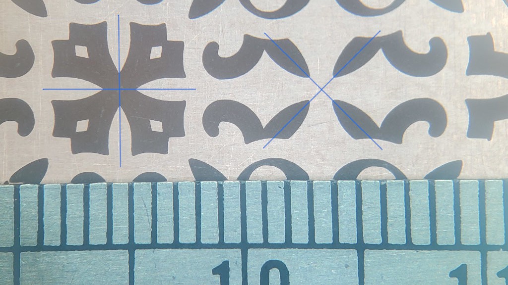
That's encouraging because milling fine-pitch circuit board features is a target application and skimming a thin skin of copper from a surface that isn't flat tests the Z axis.
Six weeks of thrash for two lessons:
- Stepper heat changes tool tip to workpiece distance by more than the thickness of 1oz copper cladding -- slowly
- DIsconnect Z probe sense from conductive material before milling
Cleverly hidden among many words below is the lack of any more useful information that you would miss by not reading any further than right here ✾ about tedious circumambulations to nowhere other than discovery that they were somewhere between mostly and entirely unproductive apart from discovery of why so.
You can still bail out now.
Heat / Temperature / Dimension / Time
If you want to hit really precise Z levels with really tight repeatability over long-ish periods of time, set $1=255 in Grbl to disable stepper motor idling, jog something to power up the motors, and do something else for ~30min--3 hrs while the heat gets around. Where "really precise"/"really tight" means variation within the thickness of copper on a 1oz copper-clad circuit board. Caveat assumptions.
It took me a while to figure that out because different parts heat at different rates with different effects. So I was seeing really good short-term repeatability (<5μm) that seemed worth pursuing, but also slow drifts over ranges too large to ignore (>100μm) in time spans comparable to milling a circuit board. Sometimes drifting up, sometimes drifting down. Considering construction with string and soft "hard"board, I had anticipated that material "settling" would be an issue, so I first tried to interpret results and try "fixes" in that light. When the spindle drifted up on a trial cut (more on that below) I thought maybe vibration made the hoist cord wrap more loosely around the pulley, in effect making the pulley larger. Or winding on additional wraps possibly eased tension on the first/lowest wraps making Z height dependent on recent history of long or short movements. And other such digressions that didn't really explain or resolve the drifts I was seeing -- and seeing drifts means watching lots of trials to discern trends, or watching and taking notes to discern trends, or watching and filling spreadsheets to discern trends, or eventually automating long runs of many consistent trials under various conditions to collect lots of data to discern long trends.
There's other stuff you could do to reduce drift by promoting thermal (i.e. dimensional) equilibrium relative to expected heating during planned work. But I'll be surprised if anyone ever needs to care about that -- so please let me know what you're doing if you ever do!
(I abandoned several starts at writing this part because it kept turning into the beginning of a dissertation and I didn't need for finishing that to get in the way of moving on with this. :-/)
So it's all good now, right? Ye....no
Having a handle on Z drift and a repeatable height map of a patch of copper, which was not flat, I started a job that started with several offset laps around the perimeter. That started out beautifully cutting laps just through the copper all around the mapped hills and valleys (relative to cut depth), totally validating totally adequate Z height control -- until the cut started getting progressively shallower.
Time, then, for a log entry about progress to that point and concluding:
The weight of the Z axis hangs directly from the output shaft(s) of the lamest of geared steppers. Missing steps would be no surprise ... if the axis was drifting down as a result of missing upward steps. How does it miss downward steps and drift up?
:-/
I have half an idea what might be happening, and a couple of ideas to try...
...and so it continues. Bah.
And indeed, so continued the bonfire of time. Neither idea worked, because I had no idea what was happening.
Eventually I established pretty clearly that the motor shaft position really was getting out of sync with where Grbl thought it was. Grbl gets a lot of use in lots of different applications and I didn't find anyone talking about Grbl itself suffering any issues with its internal notion of machine position and external sum of all step/dir signals getting out of sync. Remaining possibilities included electrical noise messing with the step/dir signals. But noise is noise and, over many trials, the unexplained Z lifting was very clearly very repeatable in terms of where in many variations of toolpath the tool mysteriously started lifting. So that ruled out a random process like electrical noise. Right?
I thrashed for a while trying to figure out what mechanical cause could make the motor skip steps upwards against gravity. Repeatably so, by some process related to features of the toolpath.
...
I'll skip a dreadful lot of narrative thrash gore here and jump to the conclusion: No. Not mechanical.
So it can't be signal noise, right? Ye....no
i.e. yes it was electrical noise.
For probing copper-clad I just use two leads with alligator clips -- one for ground and one for probe sense. Easy. Based on no information beyond naive speculation, I clip the ground lead to the bit because I figure that's the part that's less isolated from power and less unlikely to do harm to an i/o pin. And clip the more vulnerable sense lead to the inert copper-clad material. After probing I disconnect and clip the two leads together to ground the long antenna hanging from the i/o pin before starting up the presumed-noisy dremeloid. Or so I did until I got lazy running a zillion probe cycles.
Chapter summary: this extra additional further digression wouldn't have started at all if I'd continued to unclip both probe wires rather than leaving the probe sense connected to the floating copper plate.
But how could "noise" be so un-random?
I'd already confirmed that Z was stable while cutting air.
Reconsidering with confirmation that the fault was electrical rather than mechanical, it looks like signaling was corrupted mostly when the tool tip was in contact with a copper island. When in contact with the contiguous field of the copper sheet -- and the probe sense connection -- there was no problem. So the first outline of a new pocket would get cut cleanly. That seems ironic to me because I would have thought the running deremeloid would be a source rather than suppressor of noise. Maybe high but not ~∞ impedance to Earth limited static charge potential. ??. After completing an initial outline, the copper inside became a disconnected island, and apparently something about the running tool in contact with that produced noise in the probe sense connected to the surrounding copper plate, causing Z drift to drift up until it reached a small distance (50μm < d < 500μm) above the copper. So apparently there was a proximity effect as well - maybe enhanced by the sharp tool point. ??.
Sometimes a fair amount of surface would get cut before the tool drifted up too far to clear copper - especially if starting the cut deeper than normal. Re-running the same pocket would have the tool in contact with the board substrate, then it could sometimes but not always re-cut the substrate to a more nearly flat bottom before contacting the remaining copper island and cutting some more of that as the tool drifted up again. So apparently contact with the non-conductive substrate was at least sometimes ok too.
I have the vague feeling of having read, several years ago, a similar description by someone else describing their discovery of a similar problem. Is this already a known thing?
Why always up if "random"? I don't know. Maybe it was actually a random walk but biased by depth/firmness/proximity of contact to favor randomly walking up. ??.
Why just Z? Well, it probably wasn't just Z. X&Y weren't keeping position perfectly either. But what I was focusing on as "large" faults in Z would have looked like small faults in X or Y. Also X was occasionally loosing steps for mundane mechanical reasons that I was tolerating because that wasn't the main problem. So X was already showing intermittent larger errors that I was already ignoring. Compared with primary focus "large"ness of small errors in Z, and actual occasional larger errors in X, small deviations in Y looked relatively insignificant so I left that as a lesser question for later without recognizing that unexplained Y deviations weren't actually obviously smaller than the Z deviations I was fixating on.
So, back to disconnecting both probe wires. Or onward to better filtering if this project was about the electronics.
Ima calling this a working thing.
TODO: push model, cut vectors & build info
Discussions
Become a Hackaday.io Member
Create an account to leave a comment. Already have an account? Log In.
Was GRBL reading the probe and responding to it, or was the noise going into the probe pin propagating through the microcontroller and out the other pins to produce random step/dir signals?
Are you sure? yes | no
I'm pretty sure the drift wasn't coming from Grbl. I don't really know, but something about noise coming in from the floating probe wire causing spurious step signals into the stepper drivers is my current best guess. I have no idea whether that happens through or around the processor. Fortunately the oscope is far enough away from the machine to save me from falling down that rabbit hole :)
Are you sure? yes | no