 Paul McClay
(coders: relax -- not a trigger hazard)
So I'm trying to write up how to build a nouveau Z axis. The "find some string" part was getting too long. So instead I'll drop the TMI dump here to simplify that there
This design uses a bit of string on a pulley to winch up a load against gravity (or other orientation / opposing force).
The previous design already used string as part of a low cost clamp for firmly holding a round tool with flat laser cut parts.
It looks like the two uses will require two different kinds of string.
Initially I used the same kind of string for both purposes, then shifted to preferring smaller diameter string for the hoist cord, then fully committed the pulley design to use <1mm cord for the hoist. Although I haven't actually tried it, I suspect that such small diameter cord that was also strong and tough enough to use for the tool clamp would be too much like a wire saw for that job. So, two kinds of string to do two kinds of things.
The tool holder uses a “Spanish windlass” variant to firmly clamp the tool in place. I’ve arbitrarily used some synthetic, maybe nylon, 3-strand laid cord about 1.4mm diameter that was handy when I started. I thought that it might be too thin and fragile and anticipated changing to something like 2mm braided cord (which I still suspect would be "nicer" so if you're parts shopping...). But so far it’s worked well enough for that purpose that I haven’t given it any further consideration. Parts are designed for cord up to about 2ish mm diameter. The cord needs to be flexible enough to bend around its own diameter repeatedly under tension without breaking fibers.
For the new tool lift idea, I started with the cord described above. That worked ok until I started tweaking for tighter repeatability. Based on nothing, I guessed that maybe it was thick enough to affect the effective diameter of the lifting pulley but irregularly so and didn’t always wrap onto the pulley in exactly the same way every time. Other things I tried:
- single strand of three-strand cord
- fail: too frizzy to work with
- heavy sewing thread
- works well
- better repeatability than 3-strand cord
- unknown composition “extra strong for buttons, carpets, very heavy fabrics”
- seems vulnerable to progressive wear
- redundant lift is cheap insurance against sudden breakage
- low stretch holds ~constant load at ~constant length
- braided Spectra® (UHMWPE) fishing line
- works great
- tested with 50lb strength, 0.38mm diameter (nominal)
- initially appears invulnerable to wear
- redundant lift is still cheap insurance
- practically zero stretch
- retail purchase of branded product = mo$t co$tly component, but generic UHMWPE exists
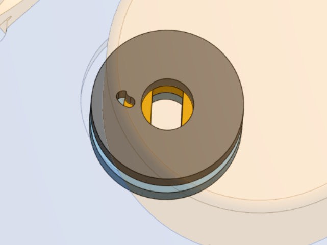
Because the pulley surface is only a few mm across, the 1.4mm cord I tried first only fit a couple of wraps on the pulley before it started to wrap back over itself, which changes the steps/distance ratio. I didn't worry about that since my application calls for precision only in the lower range of motion. I did try increasing the pulley diameter to cover the full range of motion in <two turns, and confirmed that a single motor had sufficient torque to manage that. Then I changed back to smaller pulley diameter for finer precision (more steps/distance) because, IME, the 28BYJ-48 motor steps are very unequal so two full steps is the minimum consistent stride. In the current version the pulley diameter makes two full steps ≈ 0.001"/25μm and covers the full range of motion in a little under three revolutions (plus at least a partial wrap at full extension). For ~3mm material, that requires <1mm diameter cord to fit all in one layer on the pulley.
The current design further commits to <1mm diameter hoist cord where the cord attaches to the pulley. I doubt these motors are meant to bear lateral loads, so to minimize the degree of abuse I wanted to load the shaft closer to the motor rather than hanging the load out closer to the end of the shaft. The difference is only a few mm so maybe it doesn't matter, but anyhow because mumble foo the cord attaches on the motor side of the pulley. For larger pulley diameters I could turn the cord back through the pulley to the outward face and tie a stopper knot there. Also thicker cords make bigger stopper knots. With smaller pulley diameter there's less room to turn the cord back through the pulley without committing to a very small hole or very small margin of solid material around the shaft. Also I was hunting sources of variation and preferring a short direct path to a hard anchor over a convoluted path around corners of compliant material to a compliant anchor. That favored routing through the inner (motor side) face of the pulley directly to a loop around the motor shaft. But there is a sharp stamped metal edge around the shaft with smaller diameter than the pulley. So in the latest iteration the inner pulley face has a small radial slot from outside the larger pulley diameter to inside the smaller sharp edge diameter so the cord can cross that thickness of material diagonally from larger to smaller radii. That then makes a further commitment to using cord fine enough for a knot to fit in the small gap between the shaft and surrounding sharp edge.
Also the outer end of the slot has a little hook which is an attempt to make that piece bear some of the load of turning the cord around that sharp corner instead of letting the cord act as a wire saw to cut between the two layers of the laminated pulley.
Discussions
Become a Hackaday.io Member
Create an account to leave a comment. Already have an account? Log In.