 Kn/vD
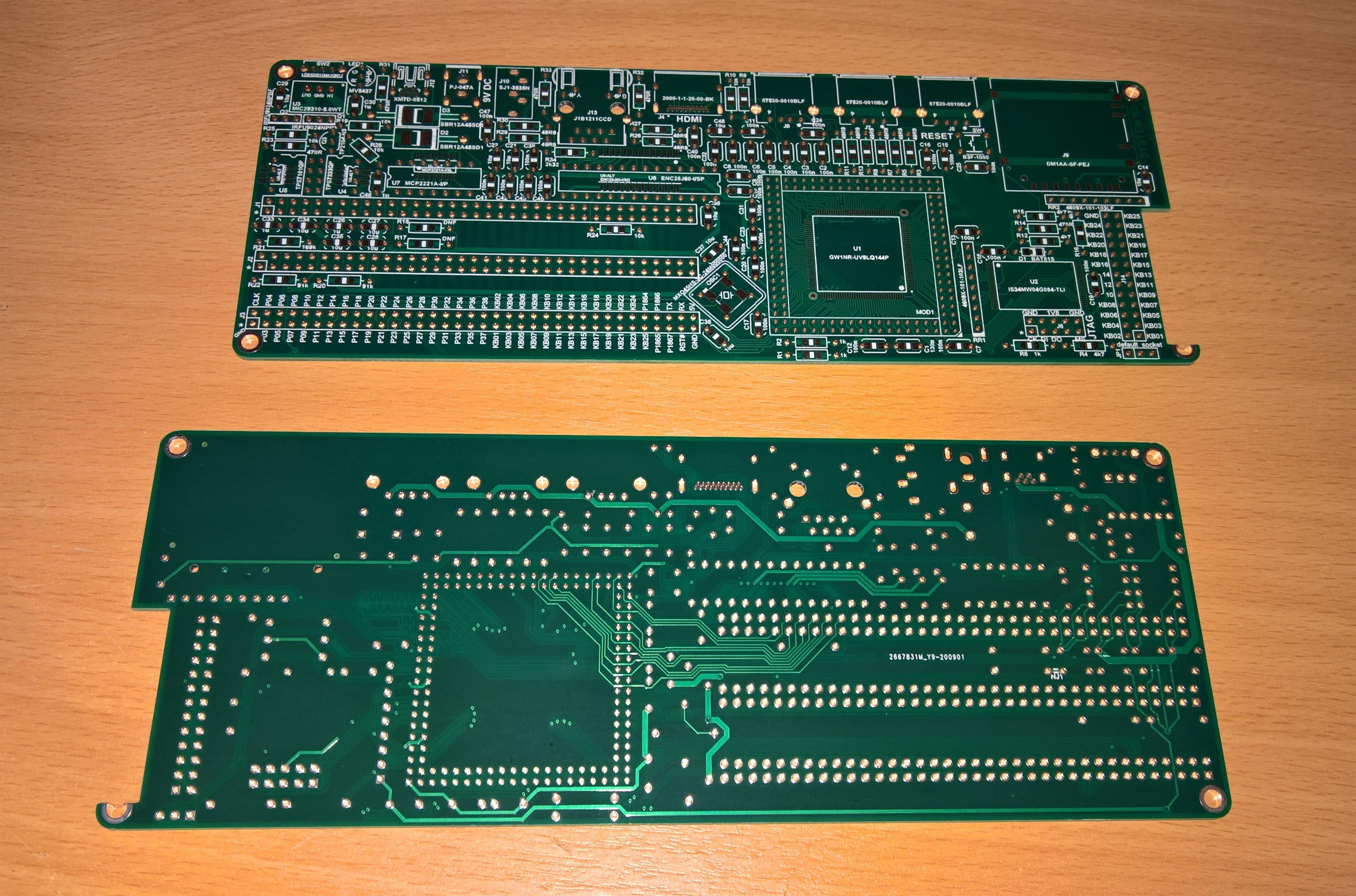
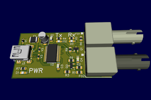
Kn/vDThe board has a number of connectors (power supply either from a 2.1mm core barrel connector, or USB), HDMI output for video, 3.5mm stereo jack, three USB ports, an Ethernet port, and also a SD card. It also has three expansion header receptacles and a header for additional matrix keyboard.
In terms of processing power, K8 is built around a very interesting FPGA from GOWIN. It is a 144-pin TQFP package (not BGA as most of the others!!!) and includes internal non-volatile bitstream memory as well as 32Mb PSRAM in addition to the FPGA block RAM. So that makes is a pretty well integrated package, ideal for the purpose. The on-board FPGA can be upgraded by installing an additional module in the emulated PGA socket around it. It can also work alongside the module. There is a jumper for setting up the needed configuration model.
There is also a separate 512Mx8 NAND flash on board, to be used as external storage. The Ethernet is handled in a simple way via SPI and ENC28J60 controller. There is also a separate MCP2221A USB-to-UART bridge to enable a lightweight console in the system.
The power supply is built from a 5V high-current LDO which provides the main power supply, from which then 3.3V and 1.8V are internally derived for the rest of the electronics. In case the power comes from the USB, the input LDO is bypassed. A bi-colour LED indicates the current mode of operation.
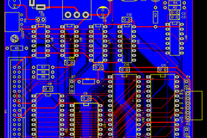
Because of the very high density of through-hole components, I was forced to do the PCB on 6 layers as there was simply not enough room for the traces otherwise. An additional complication was the need to observe the impedance and length matching for all high-speed ports, as well as an ergonomic model for the layout in order to prevent external wires crossing on top of each other, etc.
The PCB is 200 x 75 mm with a view to have it installed in a purpose-made enclosure, probably along with a separate keyboard. Alternatively an external USB keyboard can be used which leaves the keyboard header available for other needs.
The grand plan is to have a few early prototypes tested, and then hopefully offer a commercially available kit so other people can enjoy building their systems too.

 Keith
Keith
 James
James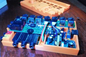
 Patrick