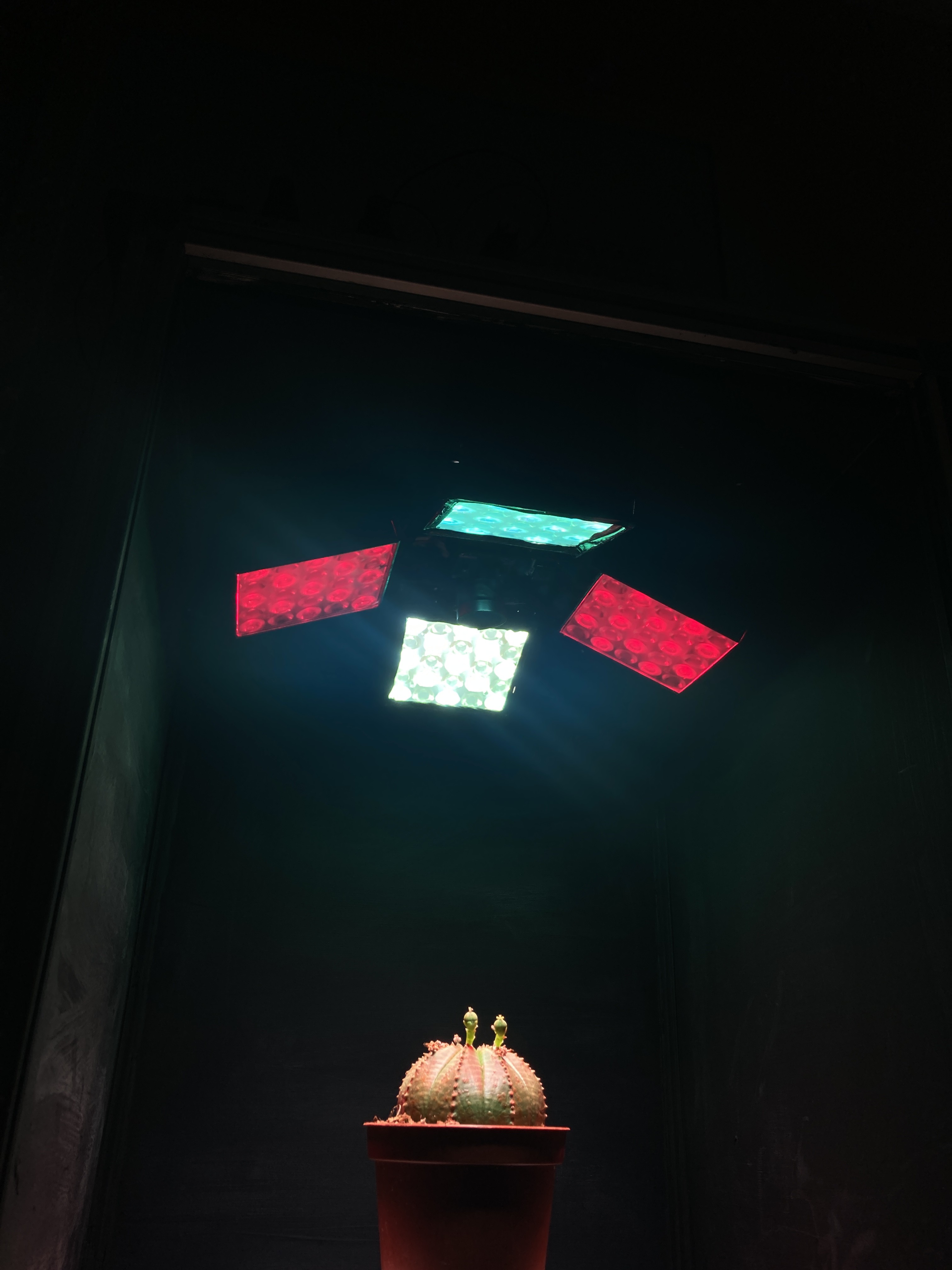
Close
0%
0%

A DIY Imaging Fluorometer

Is it possible to build a precise Fluorescence Imaging Device at home?

Similar projects worth following
Apart from being extremely fascinating, measuring plant fluorescence is also difficult. Most DIY fluorescence projects are built for educational purposes, and few of them are built with precision in mind. In the majority of cases, these projects are built around photodiodes arrays that collect unidimensional data. But what about imaging fluorometers? Well, these systems are complex and difficult to build, and depend on expensive LED arrays and even more expensive optics that can filter spurious light.
The device I am proposing here is far from cheap in the DIY sense, but it is substantially cheaper than a professional fluorometer imaging system from Waltz or any other reputed scientific instruments manufacturer. That is not to say that those systems are overpriced; surely they are much more advanced. But analysing fluorescence can also be done by using python, opencv and scikit-learn.

The idea of having an imaging fluorometer at home takes to a complete new level those of us with a keen eye for plants. Imagine, for instance, that you want to develop a more efficient LED lamp for your specialty crop, or that you are looking for ways to understand the underlying causes of stress under different external conditions such as lack of, or too much, humidity, extreme temperatures or lack of nutrients. But what does it make fluorescence to be above other well stablished techniques such as multispectral or hyper spectral imaging and/or ground sensors?

In order to answer the above question, we would have to lay some of the fundamentals about fluorescence first. 

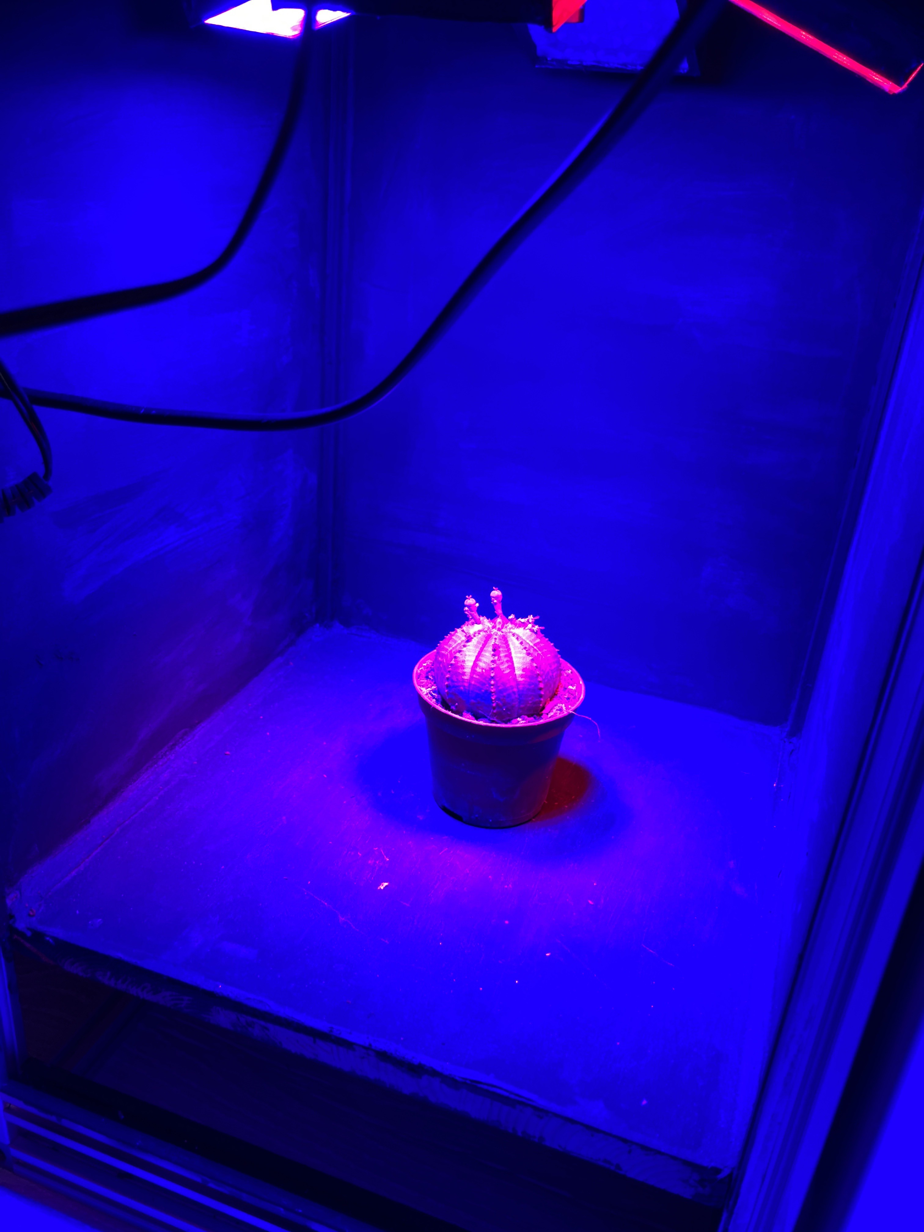
When photons reach the surface of a plant, they make the molecules of chlorophyll to get 'excited'. Literally, excitation means that the molecules absorb electromagnetic radiation from the UV-visible range of light, making the electrons to jump from a ground energy state to a higher energy state (See image below). Now, classical biology tells us that those ‘excited’ electrons will travel through other nearby Chl molecules by virtue of FRET (Föster Resonance Energy Transfer) until they reach the Holy Grail of the Light Dependent Reactions, that is, the Reaction Centre (CR), where they will finally get knocked off from the Chl molecules and transferred to the acceptor Plastoquinone. Let us bear in mind that Chlorophyll has two major absorption bands and therefore, it has two different energy levels other than ground: 1st excited singlet state (occasioned by red light absorption), and 2nd excited singlet state (a higher energy level attained from absorbing blue light, which is more energy intensive).

Chlorophyll energy states. Image taken from Buchanan et al. (2015) Photochemistry & Molecular Biology of Plants. Wiley (Oxford). pp 115

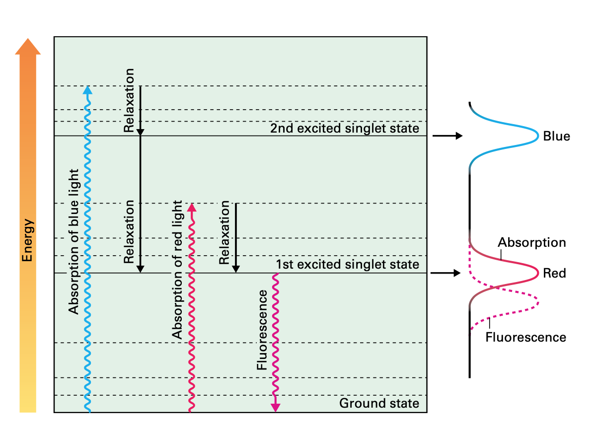
During this process, some of the energy produced by the excited molecules will necessarily be lost; as is the case when the amount of energy absorbed by Chl molecules exceeds the light utilisation of photosynthesis; such excess of energy is dissipated as heat as part of the Chl molecules returning to their ground state. Heat dissipation is always the result of vibrational relaxations that arise from the second excited singlet state. This photo-protective process is called Non Photochemical Quenching (NPQ). 

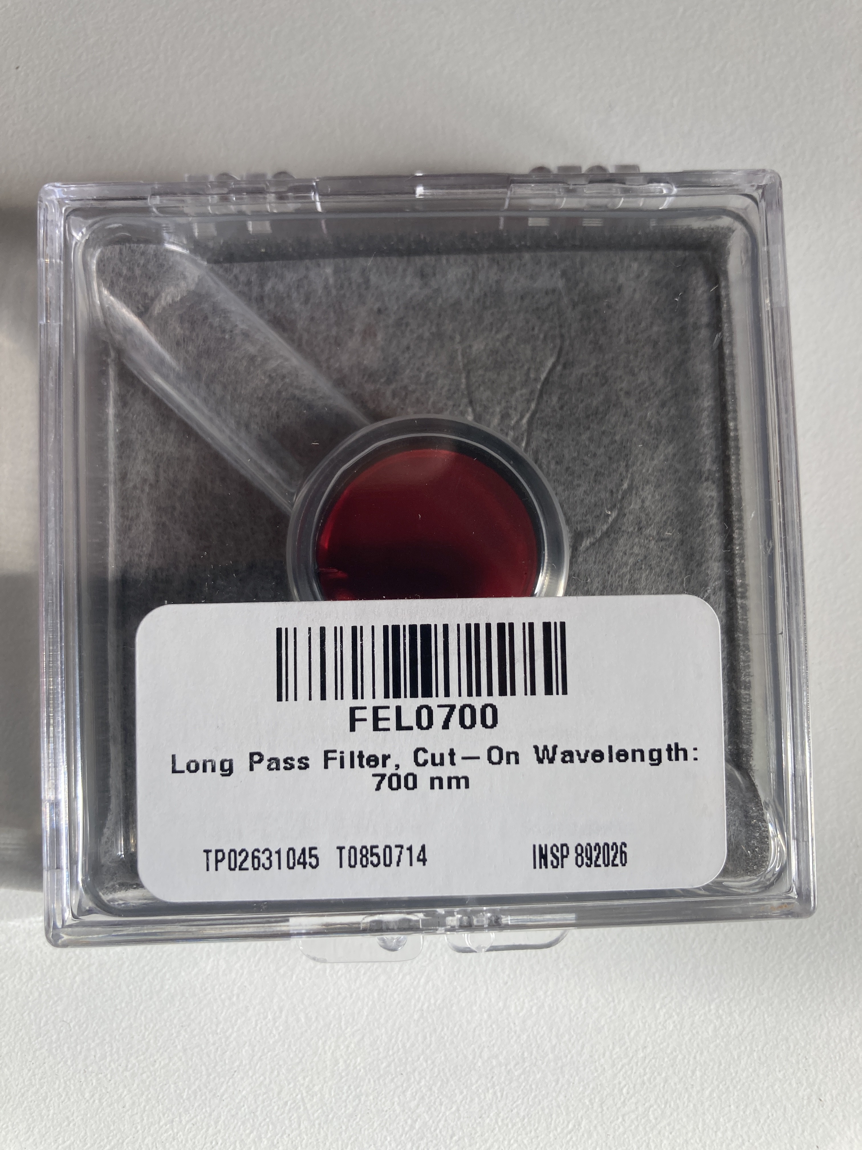
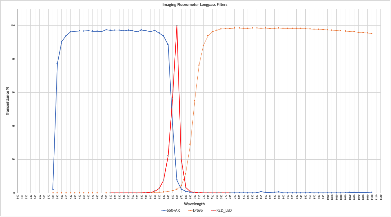
But heat dissipation is not the only way in which a Chl molecule can return to the ground state. Another mechanism involves the emission of a photon while the Chl molecule decays to ground state. Such emission is the result of decay from the first singlet state, and it has a longer wavelength (it will always be in the red portion of the visible spectrum) than the absorbed light. This final process is called fluorescence.

Now, the three processes, electron transfer, heat dissipation and fluorescence, occur against one another, which means that out of 100% of energy being captured by the Ch molecules, more or less 80% will be transferred to the RCs, around 18% will be dissipated as heat, and around 2% will be release as fluorescence. Any increment in any single one of them will mean a reduction in the other two. 

The above has huge implications when studying plants, for one thing is to measure external factors such as light intensity, humidity levels or nutrient content, and another one completely different is to be able to know exactly how many electrons are being used by a plant to sustain glucose production. At the heart of measuring Chlorophyll fluorescence is the examination of photosynthesis performance, the single most important process occurring inside a plant. 

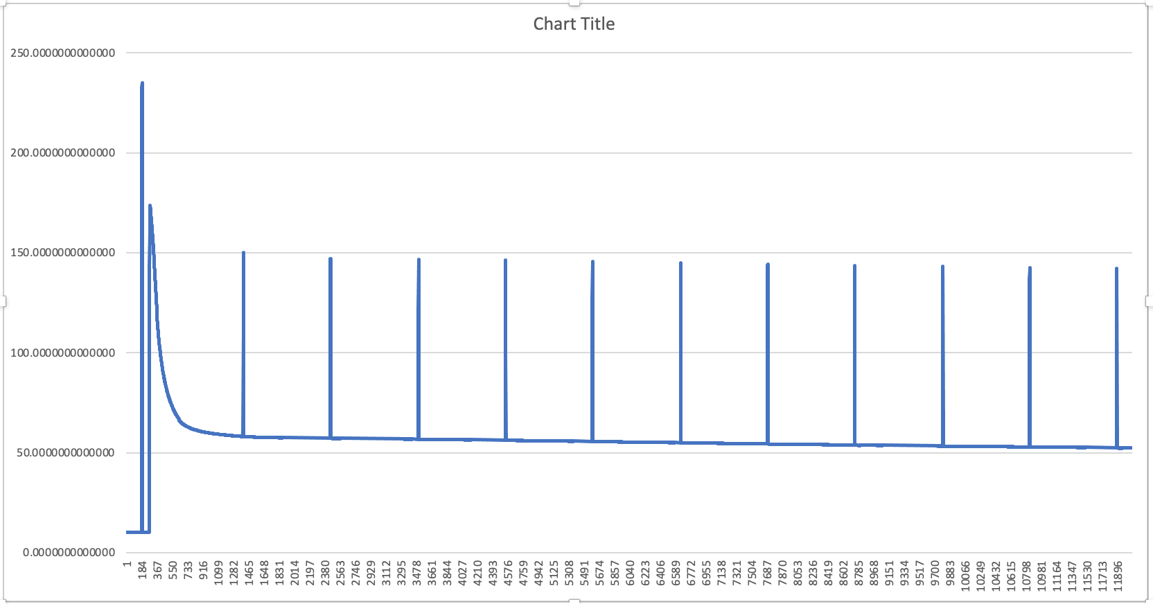
Kautsky & Hirsch Effect

In the early 1930s Professor Hans Kautsky and his collaborator A. Hirsch observed an increase of fluorescence intensity when dark adapted photosynthetically active samplea were illuminated. They published their discovery in Naturwissenschaften with the title Neue Versuche zur Kohlensäureassimilation...

Read more »

LED_Panel_Fluorometer.zip

Eagle schematic and CAM files for the 4 custom LED panels

Zip Archive - 136.98 kB - 09/23/2020 at 12:24

Download

  • 1 × Heatsink 300 X 300 mm RS-Online Stock No 264-670
  • 2 × Bosch Rexroth Strut 20 X 20 mm, 3,000 Length RS-Online Stock No 466-7219
  • 8 × Bosch Rexroth Strut Profile Corner Cube, 20 mm Groove 6mm RS-Online Stock No 466-7433
  • 1 × Bosch Rexroth Strut Profile T-Slot Nut, M4 Thread, pack of 10 RS-Online Stock No 466-7281
  • 1 × Bosch Rexroth Mounting Rim 6mm Slot RS-Online Stock No 227-674

View all 26 components

  • Finally some serious action

    Mayke06/12/2023 at 21:31 0 comments

    After procrastinating for quite some time, I decided to switch back on the box.

    The box is now tightly close with two acrylic panels. It works so good that as soon as you close it, humidity goes to the roof inside, but let's tackle a problem at a time.

    The external acrylic panel has now been painted in black to avoid light coming in, but I left a window to see inside. Not the most aesthetically appealing thing ever invented but it works. 

    Also added a small flap to keep it completely close.

    Put some seedlings inside and after few days, I could start seeing some serious carbon dioxide sinking, and very fast...

    Blue line CO2 values, as soon as the lights go on, CO2 starts to vanish inside the box. There was some leakage that I have since sorted inadvertently as the excess humidity blocked the small fisures that may be around. But humidity was really bad and the humidity sensor not only maxed out, it stop throwing non-sensical numbers. Curiously, temperature readings kept working. See humidity condensing on the panels of the box below.

    So, the quickest way to sort the humidity issue was to put some home dehumidifiers inside. After putting three, the sensor started working again, while seedlings were small, the dehumidifiers could get humidity just below 100% during the night, but as soon as lights went off and plants started to transpire, humidity got to 100% again. The massive drop is after opening the box to feed the plants. Prior to lights going on the humidity is just below 100%.

    I have noticed that plants were pointing their leaves upwards "praying position" during the night. This is sadly due to extreme humidity. Below the phenomenon can be seen in some of the seedlings. Dehumidifiers are visible too. Light and nutrients are not an issue so far, despite that extreme humidity can also bring some other problems as mould, bacteria, etc. None of that has happened in the enclosure. 

    As the plants grow, is more difficult to maintain high levels of CO2 inside so, I have decided to buy some cheap CO2 reactor, a lot of silica gel, a solenoid valve, a small axial fan and an enclosure to create a mechanical humidity filter and inject CO2 with a solenoid controlled by an Arduino.

    CO2 is being depleted in a matter of 4 hours and even less as plant progress.

    Electron transport rate (rETR) gets affected, although it's too early and the conditions not well controlled as to extrapolate the effects of CO2 levels, humidity, temperature and light levels on it. 

    You can see the Fluorescence trace recorded by the fluorometer below (same day as the two previous graphs)

    In the meantime, a batch of Thai basil (Ocimum basilicum) has been growing for 15 days in the box and this is how it looks as of publishing this:

    It's a bit crowded but leaves look perfect and absolutely healthy so far. They will stay there for another 15 days by which the Tour de France will have started and I will be absolutely absorbed and looking forward to the battle of Alp d'Huez and the Pyrenees. But in between stages, I will measure and weight my little basil plants and report back on number of leaves, size, fresh and dry weight.

    That's all for now. 

    See you in a month time. 

  • Update 05/01/2023

    Mayke01/05/2023 at 09:49 0 comments

    Hello fellas!

    It's been a while since my last update, but a lot of things have happened in the background. The machine has now been re-organised so to speak. The components have all been fixed in place, and I have added a couple of new sensors: CO2 and O2.

    The sensor in the centre of the image is the K30 from CO2Meter.com. The other sensor in red, is the O2 sensor from DF.Robot.com

    The internal components are now fixed in a two levels 'chamber' below the enclosure for plants.

    I ran out of space though, so I had to relocate some of my arduinos (I have 4 arduinos in total) to the back of the box. As I am still missing the CO2 injection control and feeding systems, it's very likely that some relays and timing will require another extra arduinos. This is how the back of the box looks like now:

    Finally, I need to seal tightly the plant enclosure, so I can measure oxygen and carbon dioxide without external interferences. I also need to keep carbon dioxide at pre-determined levels to study carbon fixation through rapid light curves and what not. The box is also getting some acrylic panels for aesthetic reasons. I have not finished that yet, but you can see a snippet in the following picture:

    I still have to do some work with the CO2 generator, which is a simple system I bought from Amazon.co.uk for £20 quid (Coca Cola bottles, nitric acid and baking soda). I am planning to use a couple of manual valves to feed CO2 and purge the box when needed; or, and that is just if I feel like doing it, I will install a couple of solenoid valves along with a relay to control the gases. The thing is, the latter option is a bit expensive and it may not be required. I also have to feed the plant with a drip form of irrigation, as I cannot open the enclosure during experiments. 

    Finally, there is that big lingering question of temperature and humidity control. In theory, I should install some temperature/humidity control mechanism so I can play with those variables too. I am also concerned about the lack of air circulation so, I may settle for an external system with vents etc. But first things first, I will finish the final adjustments (enclosure and gases control) so I can run some experiments during the last part of winter (January and February) and see how the data looks like. A big part of this machine is also software related; I want to start playing with some form of machine learning, so the box can, in a not too distant future, control the variables on the go to reach certain performance levels. All in all, it seems I will be working on this box for the foreseeable next year too!

    Oh! and before I forget, I haven't managed to sort out the F0 issue (see my previous update for a background on it). Long story short, I need to figure out how to blast the plant with 3 pulses that are no longer than 300 milliseconds in duration, and all this within one second. It turns out that I can't do that with an Arduino. I haven't put too much effort on this, but I will, eventually.  

  • Update 22-02-2022

    Mayke02/22/2022 at 19:38 0 comments

    Hey fellas

    It has been some time since my last update on the project, but I had some unexpected difficulties.

    The first one is that my Nvidia Jetson TX2 dev board developed a static electricity problem. After being switched on for some time, it would turn off suddenly. The problem just got worse so, I had to bid for a used TX2 kit on ebay (they are not common to come by these days in the UK). It wasn't chip though and I wish I would not have spent money on things I already have. In the meantime, I used a Jetson Nano as backup but the performance is not the same so, back to the TX2. The good thing is that I simply swapped my TX2 module from board to board and that was it. 

    Above: the new member of the family.

    The original idea was to test whether we could measure some important fluorescence indicators, namely, Electron Transport Rate (ETR, or rETR for relative ETR). For that we need to calculate the peaks of the signal and the valleys, immediately before the peak. Thanks to Stackoverflow and a bunch of helpful people that post on these forums, I could get this working in a matter of days. The graph below is how the data looks in one of these experiments. The plant is dark adapted the whole night, then a flash of light is applied in darkness and, after few minutes the actinic light goes on. You can see the detail on the top graph.

    We then use script.signal import find_peaks

    from script.signal import find_peaks
    

     find the peaks and valleys

    peaks, _ = find_peaks(y, prominence=6)
    valleys, _ = find_peaks(-y, prominence=1)

     and then we calculate PSII:

    # PSII Formula Fq'/Fm' (as per nomenclature of Murchie & Lawson 2013)
    PSII = (last_peak - last_valley) / last_peak
    

     with PSII and some other numbers, we can then calculate the rETR and produce a graph like the one below, where differences among daily rETR rates can be plotted:

    The savvy guys around may have already spotted a caveat from the graph with the fluorescence signal, there is no F0, which is the very dim light that is switched on at the beginning and that enables us to calculate F0. First of all, using a very dim light is very dumb in this case because the camera (already heavily shaded by a long pass filter) will not pick up the weak signal. Our second option then is to apply a very strong pulse, but I will leave the academics to explain it better:

    For a usable fluorescence image to be generated, the CCD must absorb a minimum number of photons. Increasing the exposure time and/or inci- dent, PPFD will increase the number of photons accumulated. However, when imaging chlorophyll fluorescence, increasing either of these will often impact on the de-excitation processes at PSII, a problem that is most acute when imaging Fo. Also, exposure time is often limited by the accu- mulation of long wavelength photons (dark noise). With the FluorImager system, an Fimage is generated within a 16.7-ms exposure, during which 2-􏰀s pulses (PPFD of 4,000 􏰀mol m􏰁2 s􏰁1) are applied every 300 􏰀s. Although the same number of photons could be delivered during a single pulse of approximately 110 􏰀s at the same PPFD, the long exposure time at low average PPFD has the advantage of allowing for the opening of PSII centers, thereby increasing the accuracy of Fmeasurement.

    The above text is from Barbagallo et al. 2003 (accessible in the following link)

    Another very interesting paper is Oxborough 2004 which states the following:

    For example, the generation of a usable Fo image might require a single integration period of 1 s at a photon irradiance of 1 mmol m±2 s±1. As an alternative, the same number of photons could be delivered to the sample during 10 widely spaced integration periods of 100 ms each, at a photon irradiance of 1000 mmol m±2 s±1. While the first method will...

    Read more »

  • First Experiments and Initial calibration

    Mayke10/20/2021 at 07:56 0 comments

    I have been working on the following during the last week:

    • Actinic light pulse control with the Arduino. The Arduino controls the LED driver via a PWM pin and it uses a optocoupler and a resistor to solve the voltage variation between the driver and the Arduino (10v vs 5v).

    • Light intensity control with some microcontrollers (manual stage, but will be coded all together within one Arduino code later on)
    • Light Intensity calibration using the PAR sensor and the Spectrometer

    I wanted to have 500 umoles of light under the chamber, and I also wanted to make sure that it's got the shape (or wavelengths) I want, which I use the spectrometer for. The spectrum is more or less 60% Red, 25% Blue and 15% White. That should please the most demanding plants :) 

    You can see that I have bundled up together the PAR and the fibre with the cosine corrector using a lab stand with a clamp.

    I use the spectrometer to adjust the spectra to the ratios I want.

    You can see that I had to migrate from my garage to my home office due to weather conditions (is fall in Europe).

    It has taken quite a bit of space though!

    Want to see some results?

    Above, a nice fluorescence sequence with an initial pulse, followed by 500 umoles and 2-minutes interval pulses.

    Finally, a nice picture of cactus sunbathing within the chamber!

    Back to work fellas...

  • The 700nm bandpass filter has arrived!

    Mayke10/11/2021 at 21:34 0 comments

    This filter comes from Thorlabs, expensive, but I truly doubt you can find similar quality in China. 

    I went on Sunday to one garden centre and I bought these 4 beauties.

    I applied Blue and Red light 

    And the results are amazing!

    Switching the white or red light with the previous filter would have rendered the fluorometer useless; but with the 700nm filter the only light passing through is the plant's fluorescence. The monochrome images are simply mesmerising. The false color images give us a better view of intensity distribution. 

    The next chapter is to calibrate the camera with the spectralon panel, add the Arduino to control the actinic pulses, add the measuring light (ML) to calculate Mo and calibrate the thermal camera (see one thermal image below).

  • Spectrometer arrival

    Mayke09/24/2021 at 18:41 0 comments

    After some months in sleeping mode, I finally got hold of a brand new Ocean Optics Flame VIS-NIR-ES spectrometer. 

    I also bought a fibre, a collimating lens and a cosine corrector for absolute irradiance measurements. But we still need a calibrated light source if we want to measure irradiance precisely. I will have to wait for few months, as the light source is as expensive as the spectrometer. 

    You can see the optic fibre with the cosine corrector in place and the blue and red lights on. The graph with the reading is below. The intensity is not calibrated, but I also have a very useful spectral panel that I originally purchased for the box. 

    I have also ordered a new long pass filter for the camera, as I have realised there is no signal beyond 700nm with any of the light sources and the filter (which I might not need in the end). But I also discovered that the MidOpt filter lets a lot of light in (thanks to my new toy!).

    As you can see from above, there is plenty of light coming through before 700nm, which will hopefully change with the new bandpass filter. 

    Once the filter arrives, I will start taking measurements from different plants, but we will still need the calibrated light source to finally start making precise measurements that will enable us to calculate the fluorescence parameters. 

  • Thermal Cam Assembly

    Mayke04/06/2021 at 21:10 0 comments

    I finally got my hands on a Flir Lepton 3.5 via GroupGets and I couldn't resist to see what happened when hitting a strawberry plant with a very strong actinic light (Deep Blue 450nm @ 6000+ µmols/s/m2). But before that, I had to mount the camera somehow. I am using the tiny Mini-Pro JST-SR carrier board and I struggled a bit to figure out how to attached it to the aluminium plate. For starters, the Mini-Pro does have some holes, but these are 1.2mm in diameter (Good luck finding spacers with that threading). So, I cut a small piece of acrylic and used some good ol' glue along with 2mm spacers. The trick was to solder pins to the board and then insert them into the metals spacers being filled with lead while holding the solder to keep the lead liquid. 

    The Camera after all the glue was dried :)

    Checking that after the whole mess with solder and glue, the camera still worked.

    Finally, a video showing thermal quenching with a strawberry plant. What's happening is that the excess of energy is being dissipated as heat by the plant. 

    Stay tuned for the next updates!

  • New Light Panels Assembly

    Mayke03/14/2021 at 16:21 0 comments

    Finally, after months working on a hotplate to reflow solder my LED panels, I have finally assemble the box back with the new angled-panels. 

    I have changed the colour configuration also. Now the 4 panels have blue light. This is to increase the pulse actinic light to around 6,000um. The other half have 2 white panels and 2 red panels.

    The 4 panels are covered by the filter and sealed on the sides to prevent light leakage.

    If you want to see my reflow hotplate, you can find it in the link below:

    http://maykef.co/2021/03/02/a-diy-reflow-hotplate-for-small-aluminium-core-pcbs/ 

  • Improving the Light homogeneity within the box

    Mayke09/30/2020 at 20:33 0 comments

    I have decided to tackle 'head on' the issue with illuminating the samples in the box. As you can see from the picture above, the PCB LED panels lay flat on the heatsink; that means that quite a bit of light is wasted illuminating the lateral panels, instead of the samples. To solve the issue, I decided to mount the boards on aluminium blocks cut at a 20 degree angle.

    I had the misfortune of cutting these pieces from a 4'X4' block using a mitre saw. Please do not even attempt it. Use instead a swivel bandsaw. The result will be much nicer and precise. I just couldn't justify myself to spend £500 quid on a swivel bandsaw to cut four aluminium pieces, but the motivation is there, and very likely, sooner or later I will succumb to the temptation :)

    You can also see a Russian Yasen class submarine lurking in the background. As winter closes its claws around us, and being myself from a Tropical country, I need to keep my mind busy during the coming dark months.

    You can see the preview above! I say preview as I have not finished drilling and tapping the holes for the PCB boards and I will need to rewire the whole thing. Although by the looks of it, it will be much easier than the spaghetti mess from the original. 

    Looking good! I can't wait to obliterate some alien plant with a shot of 4000 μmoles as soon as this gets done.

  • Filters and their challenges

    Mayke09/26/2020 at 12:05 0 comments

    As you can see above, the curves of the Longpass filters do not match, and that's what happens when you buy cheap filters :)

    Ideally, the blue filter should have a steep curve down the 700nm, while the orange one should have a steep curve upwards the 700nm, meaning that the blue let's light below 700nm but blocks anything beyond it, while the orange blocks anything below 700nm while letting through anything above. 

    The orange filter goes onto the camera lens, below a picture of a filter from MIdOpt, and the curve of the filter used in this project:

    Usually, the steeper the curve the more expensive your filter is. I have added the red LED emission curve (in red) for you to see that the blue Longpass filter should cover it, which means that should allow most of it, which is not the case. 

    I have requested some quotations from Chinese manufacturers as a filter 76X76mm in size would cost a fortune in the UK or the USA. It is not that the Chinese will give it for free, but we can expect a 50% reduction in price, probably at the expense of some quality.

View all 11 project logs

  • 1
    Building the Box

    You will need the following cuts:

    • 12 x 300mm
    • 4 x 520mm

    Upper part:

    Take 4 x 300mm, 4 corner cubes and the heatsink. With the heatsink flat surface pointing down, put the 4 profiles around and assemble them using the screws and the cubes. No need for drilling as the profiles will compress around the heatsink keeping it in place.

    Bottom part:

    Take 4 x 300mm profiles, 4 cubes and the 4 x 520mm profiles. Tight the screws in the three different directions. Place the other 4 300mm profiles at 100mm from the bottom up and use the Gussets to keep them in place. The Gussets should be placed below the profiles. 

    Present the upper part at the top of the 4 520mm profiles. Do not tight the screws linking the whole box just yet.

  • 2
    LED PCB Assembling Boards

    Part 1:

    • Blue/Red Panel x 2

    Part 2:

    • White/Green Panel x 2

    Part 1 assembling:

    Take 13 Blue LEDs and 12 Red LEDs for the first panel.

    Take 12 Blue LEDS and 13 Red LEDs for the second panel.

    Part 2 assembling:

    Take 13 White LEDs and 12 Green LEDs for the third panel.

    Take 12 White LEDs and 13 Green LEDs for the fourth panel.

    Follow the order below:

    If you do not have the oven at home, you will have to send the parts to be assembled elsewhere. Another option is to request assembling when requesting the PCB boards from your favourite PCB manufacturer. 

  • 3
    Camera and LED Panels mounting

    Here is where the fun starts.

    Find the centre of the heatsink and drill a 16mm hole. This is to accommodate the USB 3 cable to connect the camera and the LEDs wiring.

    Put the USB cable through the hole and connect it to the camera. Please the camera onto position and draw the position for the 4 holes. For M2 screws, use an 1.8mm drill bit. Tap the threads with an M2 tap. Use metal spacers to place the camera.

    From the centre hole, draw a square of 80 x 80 which will guide you to place the four boards aligned. Mark with a pencil the corner holes and drill them onto the heatsink using a 2.8mm drill.

    Tap the thread using an M3 tap into each hole. Place the boards and secure them with M3 screws.

    The same colour panels are connected in parallel. That means that you need to connect the positive connector to the negative of the other board. 

    To close the circuit, you need to connect the positive wire from the LED driver to the positive of the first board, then the negative of the first board to the positive of the second board and, finally, the negative of the second board to the negative of the LED driver. 

    Your wiring does not need to be as ugly as mine. As a matter of fact, I originally created a whole PCB board of the size of the heatsink to prevent all these wires running amok. But in later stages I decided to go for individual PCBs for each lamp due to the lack of available lenses. I settled for the VIRPI lens of Ledil which, in turn has created problems of its own. Mainly the fact that I need to create an angle to illuminate the samples uniformly. See the Photon Systems Instruments Open FluorCam. 

                      Image taken from Photon Systems Instruments Instructions Manual p 17.

    Another question you may have is what are the small PCBs for? Well, the lamps are too powerful to fulfil the requirement of the Measuring Light (ML), which is illuminating the sample with a beam of less than 1 umol. I will deal with that in one of the Project Logs.

View all 4 instructions

Enjoy this project?

Share

Discussions

Similar Projects

Does this project spark your interest?

Become a member to follow this project and never miss any updates