Are you interested in using the Arduino to control a wheeled robot? I'm sure that at some point, you wanted to control your own robot. However, there is always a big problem: I don't have a robot with wheels. How do I test my programming control logic?
I, too, always asked myself this question, when I didn't own my own robot. It was for this reason that I built the Printed Circuit Board Robot Car with the JLCPCB Company.
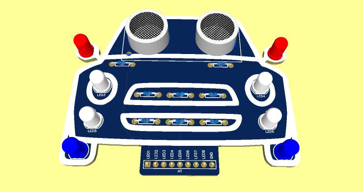
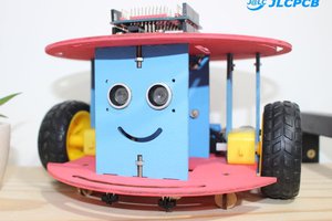
Figure 1 - JLCPCB Robot Car Printed Circuit Board.
Next, we will present the complete structure to build the Arduino-controlled PCB Robot Car project.
Developing the JLCPCB Robot Car with Arduino
The JLCPCB Robot Car was developed with 8 LED's and an ultrasonic sensor to detect obstacles. As you can see, the 2 blue LEDs are used to represent the robot's wheels.
In addition, we have 2 red LEDs in each rear view mirror and 4 lighting LEDs on the front of the car.
With these 8 LEDs, we can do several types of simulations. Through them, you can, for example, signal the movement forward, backward, left, and right.
In addition, activate some LEDs when the object is very close to the car.
Did you like the possibilities of things that are possible to do with the JLCPCB Robot Car? If you liked it, let's understand how to build our own JLCPCB Robot Car with Arduino.
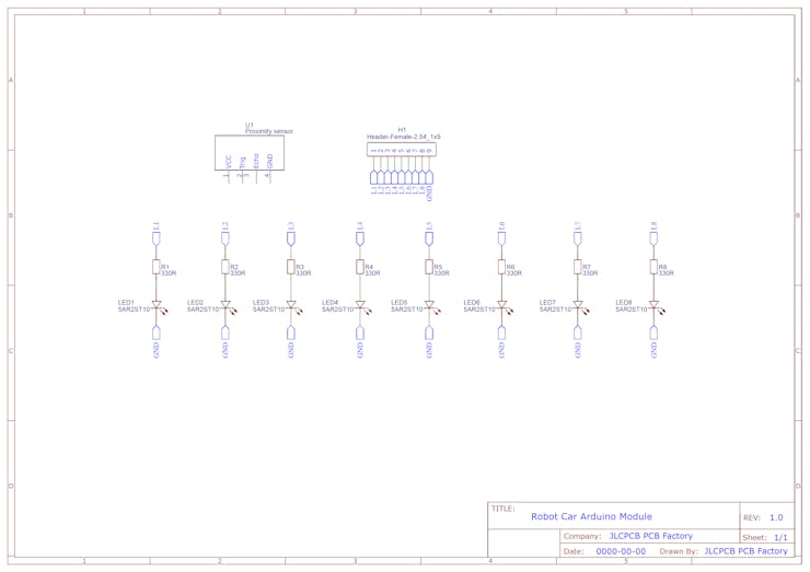
Figure 2 - Electronic Schematic of the Project.
The schematic above shows the connection structure of the circuit elements of the electronic board.
From this electronic scheme, the electronic board was developed. The electronic structure of the board is shown below.
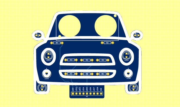
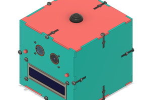
Figure 3 - Printed Circuit Board without electronic components.
The structure of the board is quite simple and allows it to be connected to a protoboard.
In addition, there are holes that allow the attachment of the ultrasonic sensor to the rear of the JLCPCB Robot Car.
From there, you will learn how to create logic and use your JLCPCB Robot Car with Arduino.
For this, we will solve the following problem:
Draw up a project to deflect the JLCPCB Robot Car with Arduino when it detects an obstacle. The robot must turn to the right, activate the rearview LED and continue after it is out of the obstacle.
Now, let's get our hands dirty and develop this project.
Development of the JLCPCB Robot Car with Arduino
First, we must build the circuit in the figure below. This circuit is formed by the sensor and the LEDs of the car with wheel and headlight.
_wnHGmvoie7.png?auto=compress%2Cformat&w=740&h=555&fit=max)
Figure 4 - Electronic Circuit in TinkerCAD Software.
From this circuit, the programming logic below was created. This logic is intended to simulate the diversion of the car from any obstacle. If the car is less than 30 cm from the obstacle, the car must turn on the LEDs and start the engines, so that it can change direction.
The LED's will turn off when the vehicle moves away from the object, that is, when the distance is greater than 30 cm.
#define echoPin 9 #define trigPin 8

long time = 0;
int measure = 0;

void setup()
{
  pinMode(2, OUTPUT);  pinMode(3, OUTPUT);  pinMode(4, OUTPUT);  pinMode(5, OUTPUT);    pinMode(trigPin, OUTPUT);  pinMode(echoPin, INPUT);

}

void loop() {
  digitalWrite(trigPin, LOW);  delayMicroseconds(2);
  digitalWrite(trigPin, HIGH);  delayMicroseconds(10);  digitalWrite(trigPin, LOW);
  time = pulseIn(echoPin, HIGH);
  measure = time * 0.034 / 2; // Speed of sound wave divided by 2 (go and back)
	  if(measure <= 30)  {    digitalWrite(4, HIGH);    digitalWrite(5, HIGH);    digitalWrite(2, HIGH);    digitalWrite(3, LOW);  }    if(measure > 30)  {    digitalWrite(2, HIGH);    digitalWrite(3, HIGH);        digitalWrite(4, LOW);    digitalWrite(5, LOW);    digitalWrite(3, LOW);    digitalWrite(2, LOW);  }

}
The operation of the program is quite simple.
Initially, names for the ultrasonic sensor connection pins were declared and, also, the program variables were declared. The code portion is shown below.
#define echoPin 9 #define trigPin 8

long time = 0;
int measure = 0;
Next, we declare the void setup function. This function is used to...
Read more »
 Jithin Sanal