 Bharbour
This project re-uses a few boards from previous projects and adds a couple of new ones. Some software ties everything together.
Existing boards:
LED Matrix Driver boards. On the front side of the chassis.
SmallPi SAMD21J18 controller board. The middle board on the back side of the chassis.
GPS Receiver board. The leftmost board on the back side of the chassis.

New Boards:
Ambient Light Sensor board. Lives next to the leftmost display module on the front of the chassis.
DIP Switch board. Visible sticking up on the wiring harness.
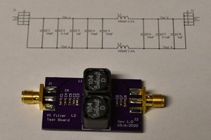
Input power filter/regulator board. The rightmost board on the back side of the chassis.

Communication with the LED Matrix modules is via an I2Cbus. There are 18 devices on this bus, so it can get pretty busy at times. It clocks at 400KBPS and the bus is spread out over about 18" of wire. I was a little concerned about this many devices that are spread out over this much distance, but it looks reasonable on an O'scope and I don't see any signs of data errors in operation. The ambient light sensor and the DIP switch are also read over an I2C bus. A different bus was used for these two just to separate them from the display module traffic.
When I started the project, I thought about developing all of the firmware for the project on my desktop machine and then porting it over to a microcontroller when all the features were implemented. This is why I chose to put the DIP switches on the I2C bus (with a TCA9534 I/O Expander chip). It is also why I picked an Ambient Light sensor module with an on-board ADC (BH1726NUC-E2). In the end, I decided it was not worth the effort on a project this size to take this approach and just did the development on the SAMD21J18 part.
Communication with the GPS receiver is done with a UART. It is running at 4800baud which is the "standard" for NMEA traffic.
A serial debug console connection is also available. This will mostly be used to see what the GPS reciever is doing. The Copernicus II seems to be a pretty generic GPS receiver. The sensitivity is OK but not outstanding. I suspect that running this in our wood framed house with asphalt shingles may be marginal for getting a fix unless it has a window view. Time (and the debug port) will tell on this one.
The SAMD21 family uses something they call Sercom modules to support UART, I2C and SPI communication. I wanted to run 4 of them for the communications described above. The SAMD21E18 only has 3 of those modules accessible, so that drove the choice to use the SAMD21J18 based board.
I started using the Copernicus II modules in another application several years ago. I had most of the software to parse and control these modules left over from that. It still took some work to add parsing for a couple of additional messages and control over a couple of aspects of the receiver. Also, the original code was developed to run in a lot fatter environment, so there was a lot of error handling and parsing of marginally useful stuff that needed cleaning up.
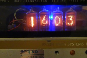
All timekeeping is done in the GPS receiver. The firmware that is running on the SAMD21 parses the NMEA messages from the receiver, converts the "Time of Week" output value to local time and day of week, and formats it for display. I thought a lot about doing the timekeeping in the SAMD21 processor and disciplining it from the GPS data. If the GPS fixes inside my house prove to be intermittant, I will implement the local timekeeping, but I wanted to see whether this idea would work.
Time is extracted from the NMEA messages from the "Time of Week" parameter. "Time of Week" is the number of seconds since midnight on Saturday night, in GPS time. GPS time differs from UTC time by a varying amount. When this was written,...
Read more »


 Ken Yap
 Alan
Alan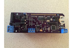
 Nick Sayer
Nice work. 👍 Wish I was as handy with case construction as you are.