(Tipp: click on the pictures to have a bigger version)
As mentioned above this device measures the AC current flowing through the attached load. Of course, different approaches are possible to measure the current, I chose a solution that is based on the ACS712 sensor IC.
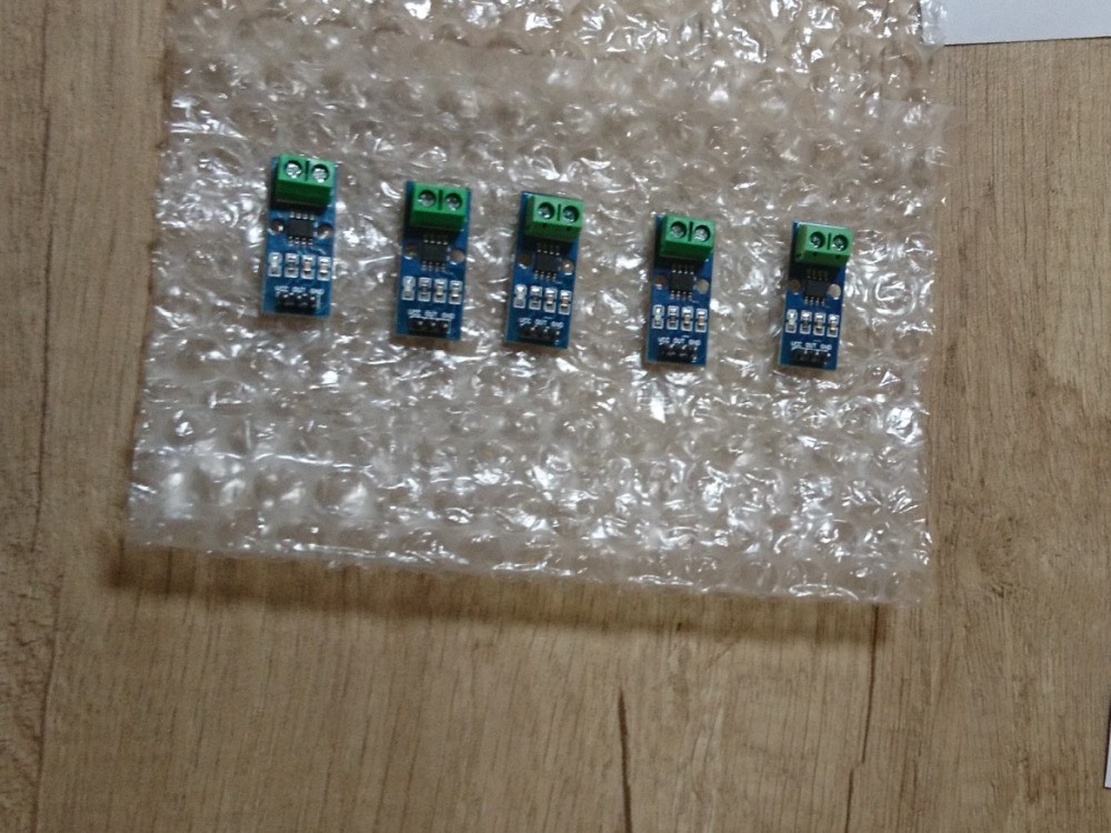
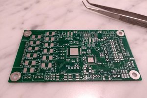
First of all, I do not recommend to use these Chinese ACS712 breakout boards (or at least not each type):
As you can see the isolation between the main-voltage (AC 230V in my country in Europe) and low voltage (towards the microcontroller board) parts may be different depending on the particular model. Here I show you two different PCB layouts, the one on the left-hand side has more clearance (marked by a green rectangle), where the device on the right-hand side has a very-very small trace spacing (marked by a red rectangle). HOW should this thin gap provide adequate electrical isolation??
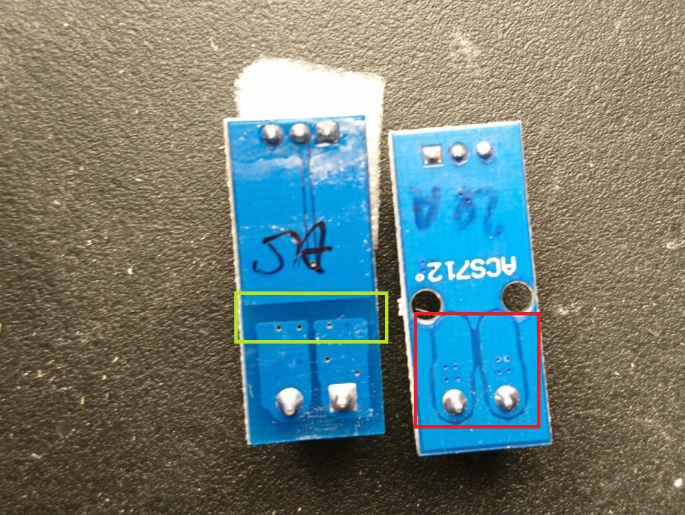
I used this board, where the clearance is much more bigger, it can be seen that the designer/engineer of this device considered the voltage differences between the two parts.
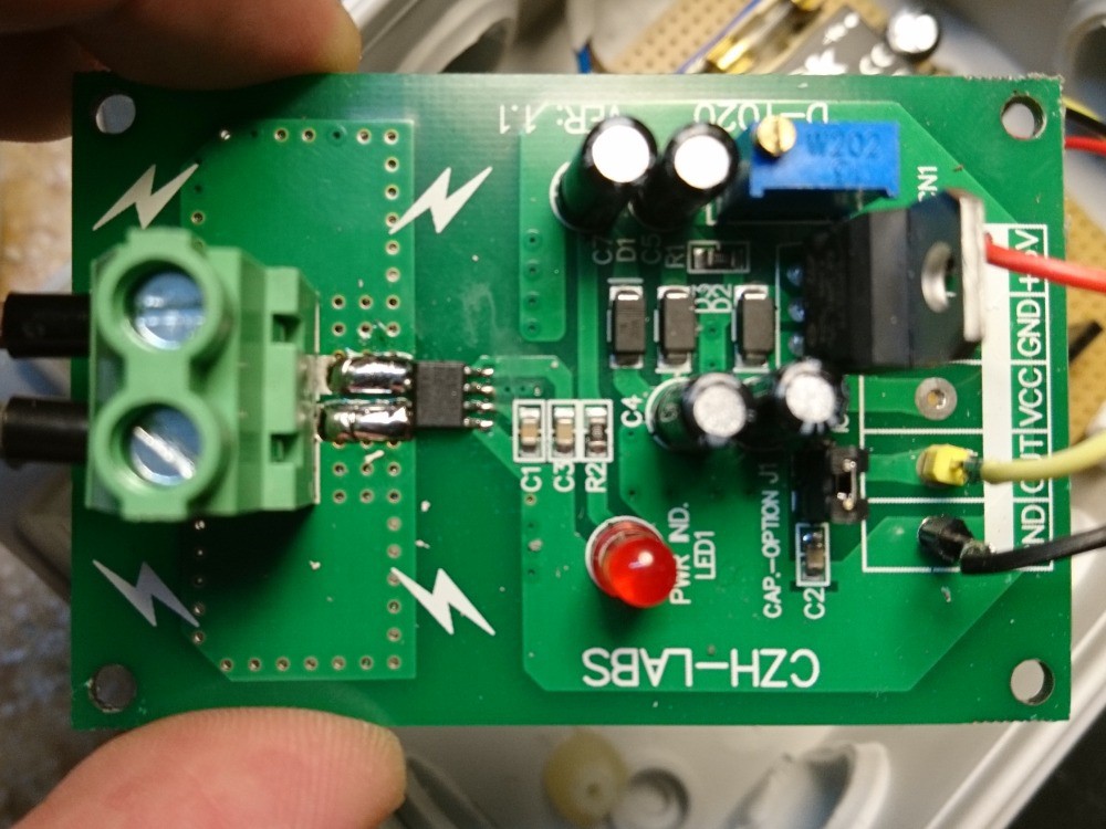
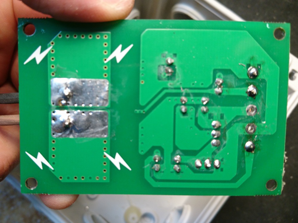
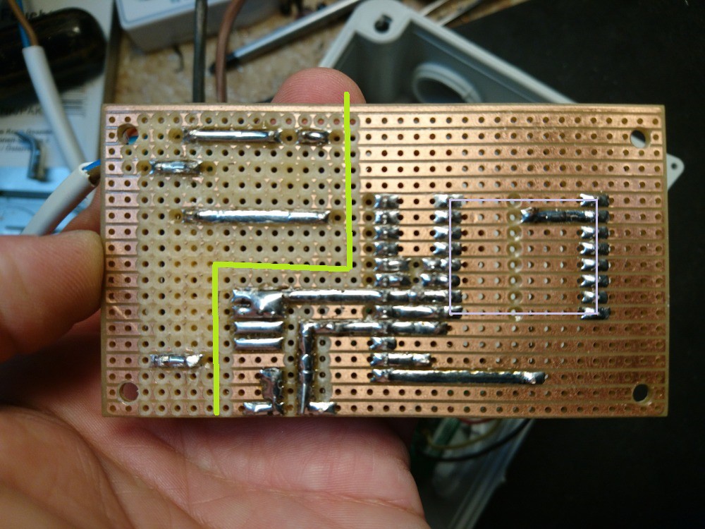
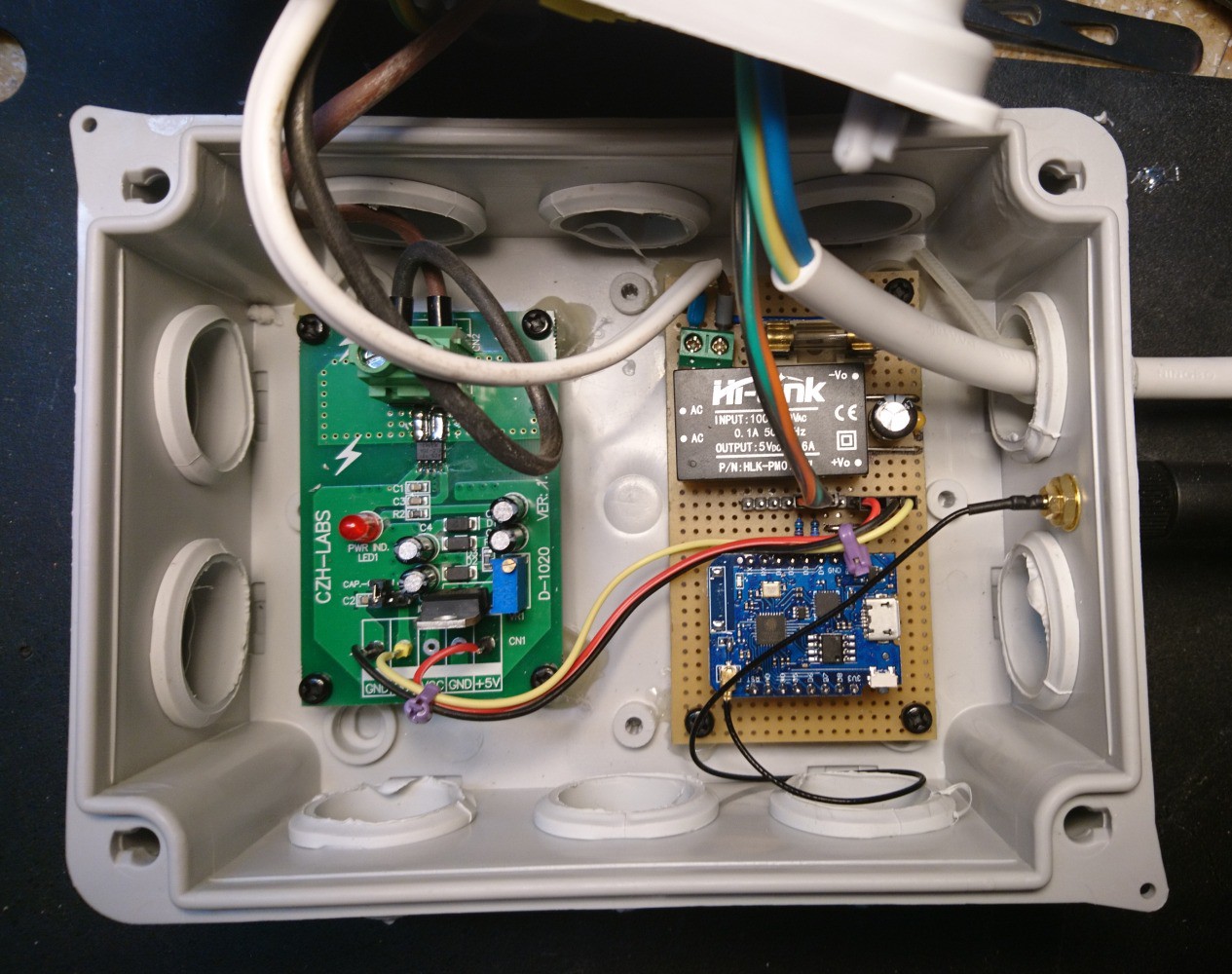
I also tried to make good electrical isolation on my own board (see the yellow line below). Since the circuit is very simple I did not designed a PCB, but used a piece stripboard as my prototype PCB. The soldered pins of the ESP8266 (or actually its socket) is marked here by a light blue rectangle.
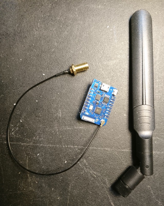
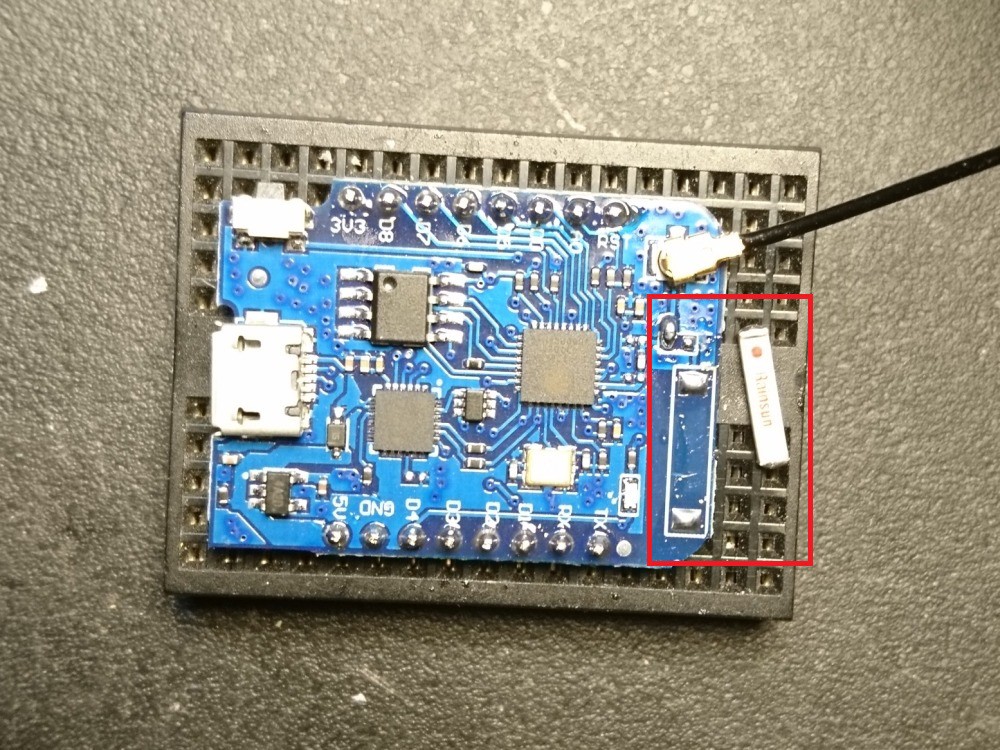
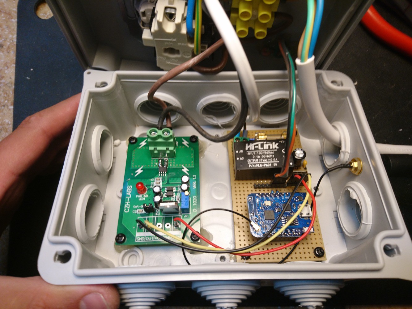
Because I will install this device in the basement, where the WiFi signal level may be lower I used a so called Wemos D1 mini Pro board, which has IPEX/UFL connector and I attached an external WiFi antenna. (If you also want to use external antenna do not forget to do the needed changes on the board, in my case a zero ohm SMD resistor was applied to lead the signal to the soldered ceramic antenna, see red box below).
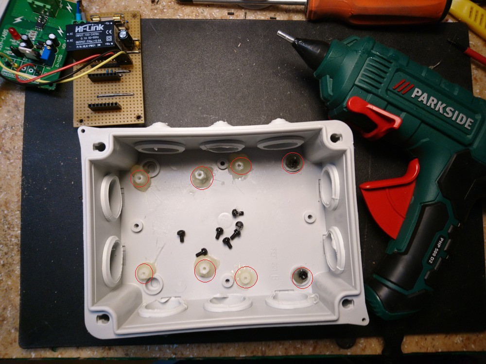
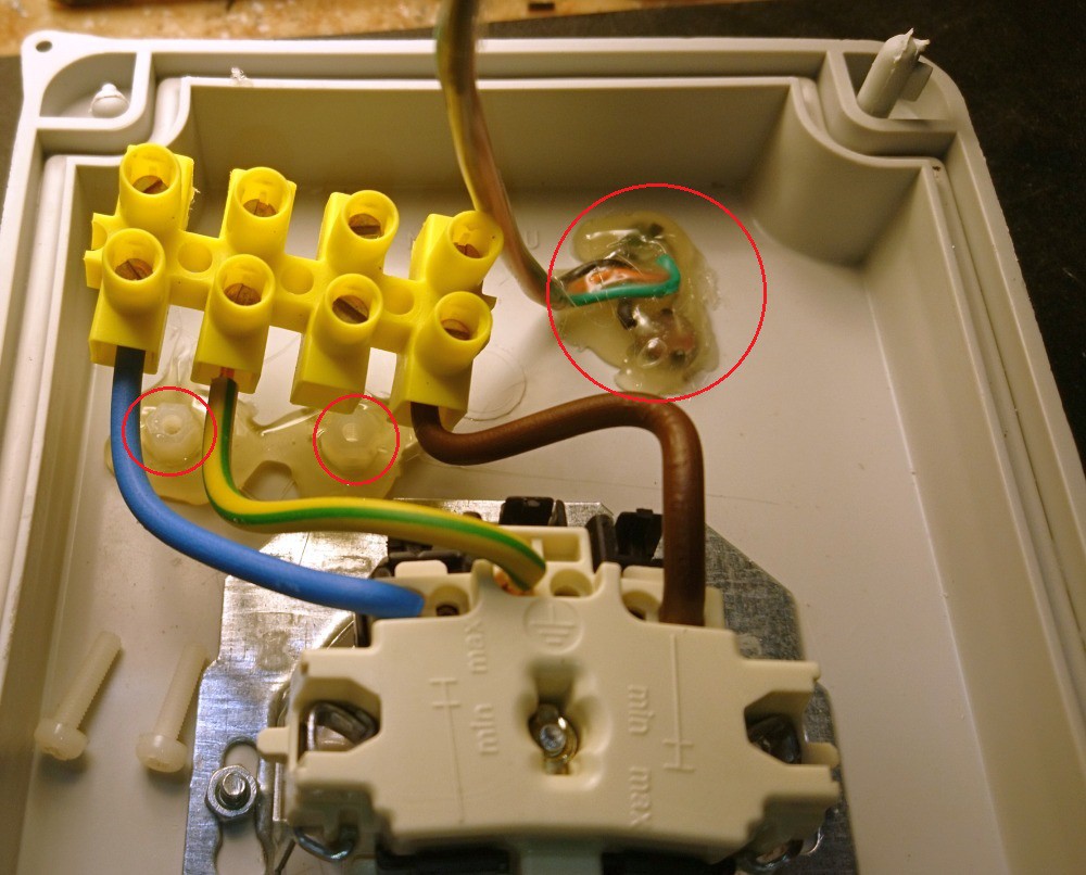
Regarding the case: I used an IP45-rated junction box. The boards were mounted with screws, I used plastic placeholders (see red markings below) that I fixed with hot glue.
Also the terminal block was mounted in similar way. On this picture the back of the green and red LEDs can be seen as well, they were also fixed with hot glue.
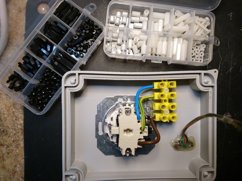
The plastic white and black placeholders...
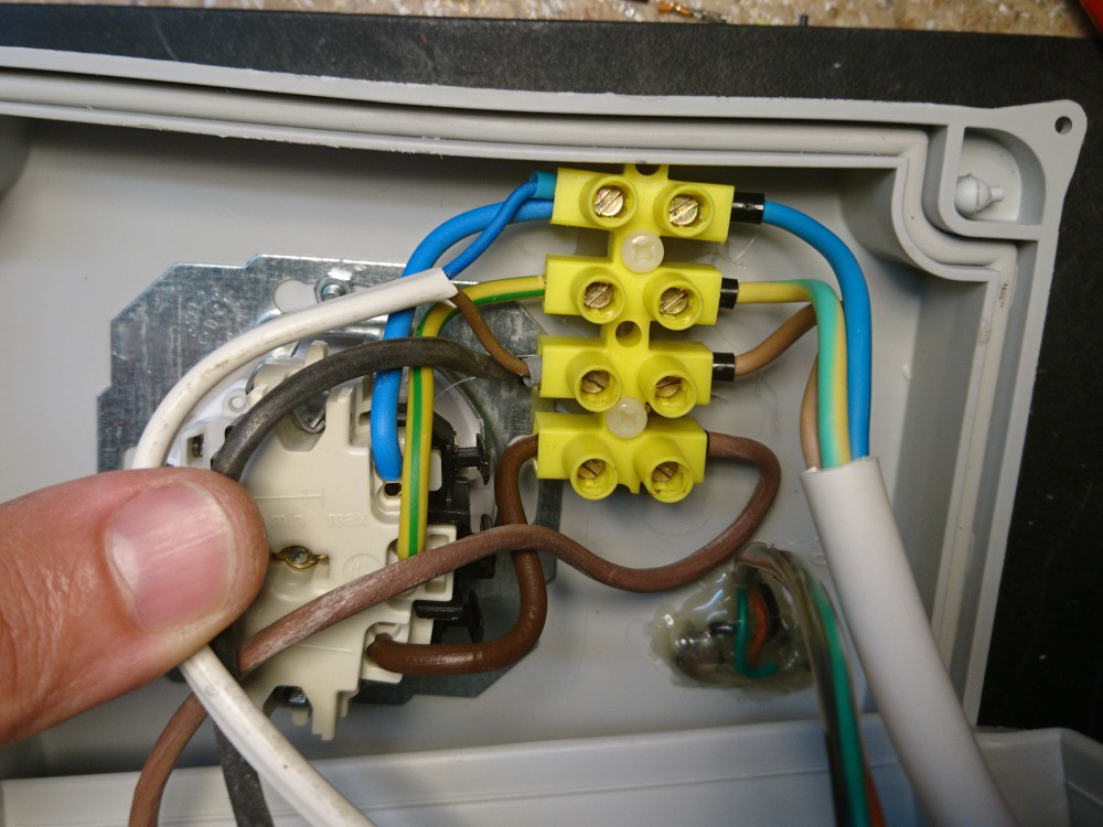
The back of the electrical outlet and the terminal block again. I used 2,5mm2 wires for the electrical socket and for the current sensor module, and 0,75mm2 wires for my uC board.
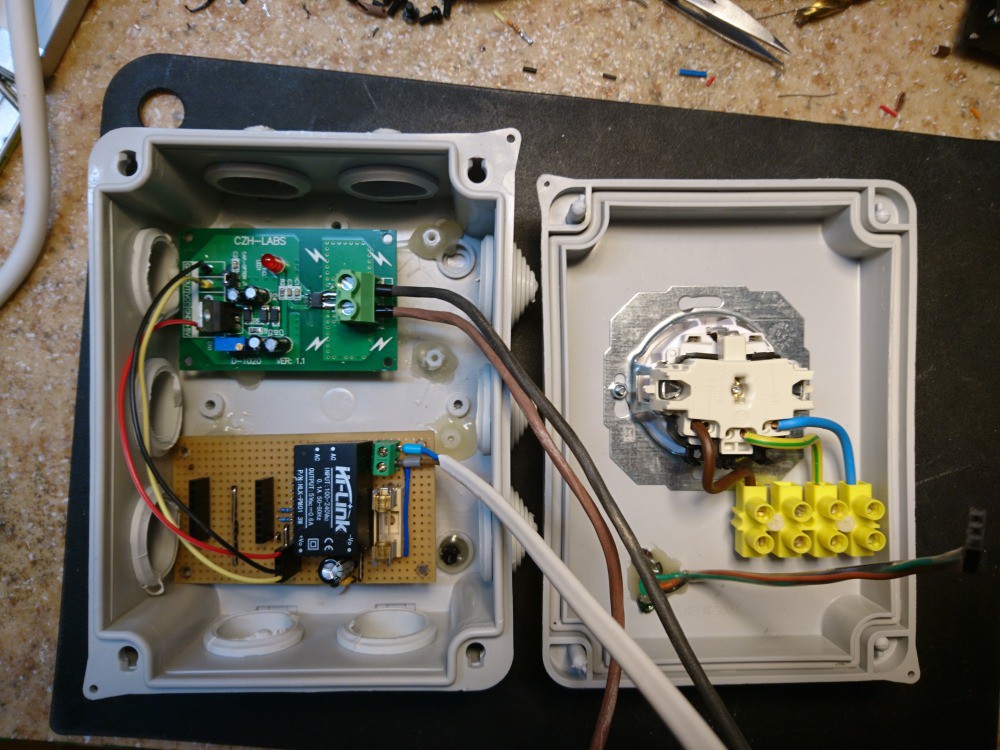
Some more pictures...
I will extend this description:
- circuit diagram, brief explanation of the parts
- explanation of the features/functions/operation
- part list
- source code

 Rory
Rory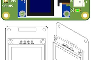
 hesam.moshiri
 Torbjörn Lindholm
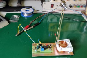
Hi Istvan,
I also want to build a device like this. Since I want to detect if the machine has finished, I have to deal with low currents (a few LEDs are lit and the programme-controller need a bit too. Even after finishing, the machine turns the load from time to time. So my first problem is the selection of the current-sensor. I suppose the heating will consume about 2kW, which gives a bit less than 9A - my current sensor (hall-effect type) is a 5 A type. I think that will not be a problem. But how do you determine the end of the washing-programme?
I am waiting for your code and hope to get some tips from it.