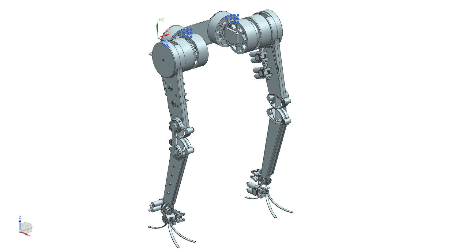
The robot uses two mirrored legs with 2 DOF in the hips (ab/adduction and flex/extension), 1 DOF in the knee (flex/extension), and 2 DOF in the ankles (in/eversion and plantar/dorsiflexion). I tried to keep all the motors for the actuators as close to the hips as possible, but I did opt to stack the ankle hydraulic actuators on the inner thighs, rather than trying to put them on the pelvis area since I was hoping it would theoretically help to keep the center of gravity over the feet while the knees are at "rest" at 148 degrees.
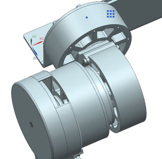
Starting from the top and working down at the hip: you can see the hips use DCBL motors that drives the ab/adduction motion. The design for these DCBL motors is based on the design from Benjamin G. Katz at MIT in his thesis "A Low Cost Modular Actuator for Dynamic Robots". The ab/adduction motor is then secured to the flex/extension motor using an aluminum bracket, which is bolted in using M3 bolts (all fasteners on this robot are either M3 or M1.6 bolts, with theoretically all holes being tapped to mitigate the need for added weight in lock nuts. All bearings and attached axles would require an arbor press to assemble). Then, the flex/extension motor bolts to the knee motor using another milled aluminum bracket.
The knee uses a "spindle" which is bolted directly to the outer-most DCBL motor's rotating platform, while the structure of the thigh link is bolted to the stationary portion of the motor. The mechanism of the knee gave me a lot of trouble. In Katz's paper, he uses a belt and gear-driven system, similar in principle to how mine is designed, but with serious drawbacks in rigidity and stiffness. To combat this issue, I opted for a dual-direction cable design inspired by the LIMS2-AMBIDEX elbow joint from CMU.
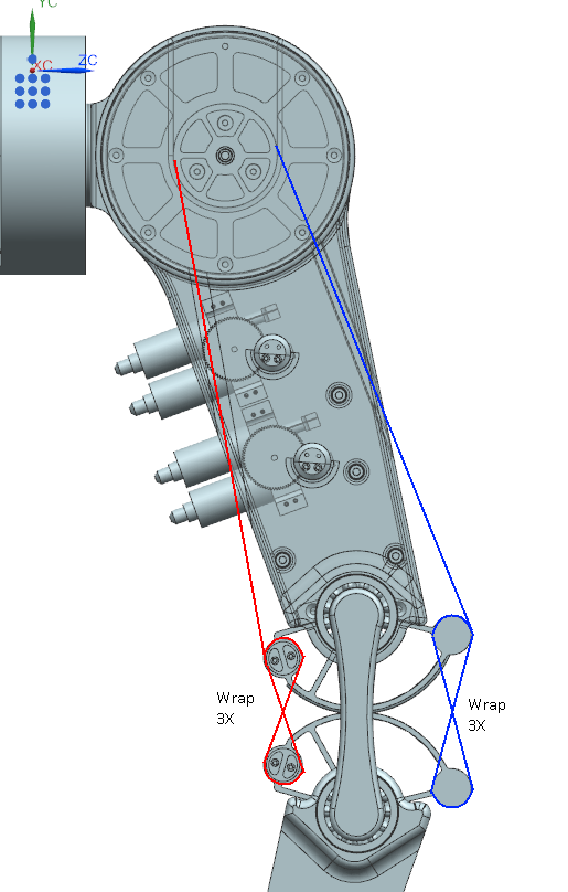
Two wires are wound in opposite directions around the knee spindle that sits near the hips. These wires then travel along the length of the upper leg link (~20cm long as specified in the assignment document) and actually pass outside the aluminum shell to meet up with the knee rollers through slits that run up the thigh. The knee joint itself consists of two mirrored "rollers", that roll along two semicircular grooves (with taught wires passing between the mating surfaces to ensure pure rolling and no slipping in the joint). On the outside of the leg, as pictured above, the wire will wrap around two wires spools 3 times, linking the two rollers together, and securing itself to the upper spool. This same idea is mirrored on the inside of the thigh, but the wire is wound around the spindle in this opposite direction. This way, if the knee motor turns clockwise, the wire pictured in red above would bring the back of the knee joint together, and the wire pictured in blue would allow the front of the knee to pull apart. If the knee motor turns counter-clockwise, the opposite action occurs, with the red wire unspooling and the blue wire tightening. This whole mechanism is secured using an aluminum link between two ball bearings found on McMaster-Carr.
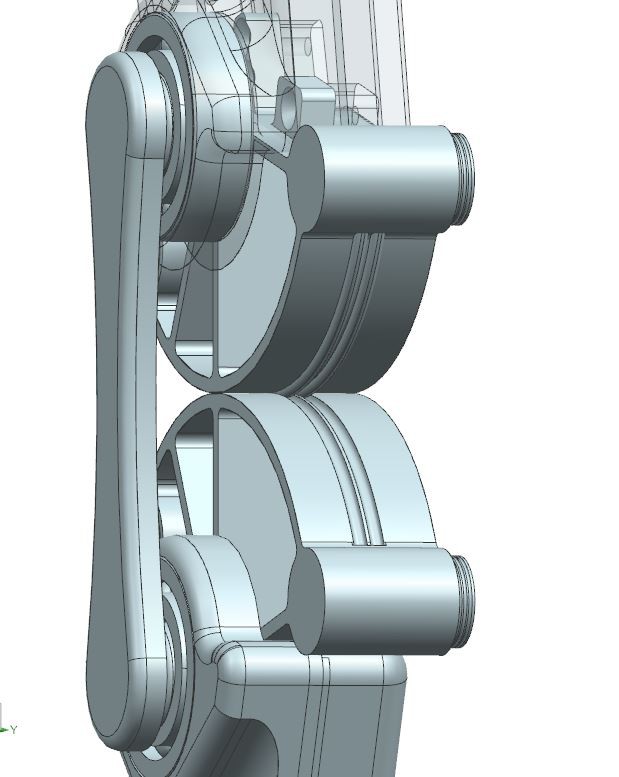
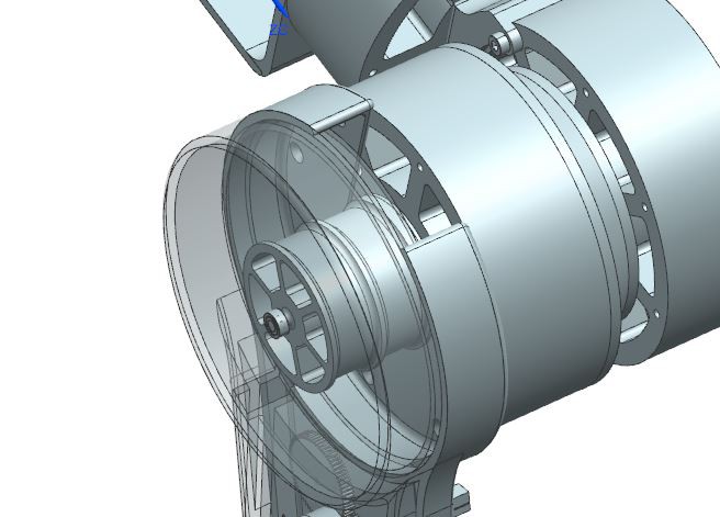
Here you can see the grooves the knee rollers ride along to reduce the chance of lateral slipping,
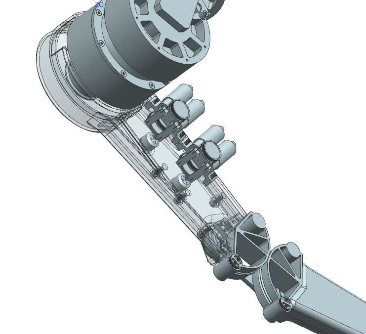
And here you can see a better view of the inner thigh and how the roller system is mirrored on both sides. This view also showcases the location of the hydraulic actuators powering the ankle joint.
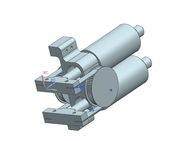
This is the hydraulic actuator I created based on the Disney Robotics model. This actuator is great since it can be used at both the driving and the driven ends of the joint actuation system. In the image above, the two stacked cylinders encase the membrane/piston system demonstrated by Disney, with a generic fluid hose connector on the far end, which would be used with a thin flexible hose to link both ends of the actuation. The plungers in the pistons are connected to a rubberized belt, which passes over a gear and then links to the other piston. In this system, whenever one piston applies a positive pressure, the opposite piston applies a negative pressure....
Read more »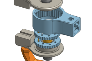
 Tim Wilkinson
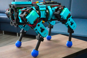
 Aaed Musa
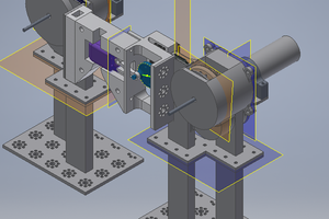
 Silas Waxter
 Charles Galambos
This is amazing, thanks a lot for sharing! What's the benefint of the hydraulic transmission compared to stand-alone small BLDC motors? I imagine that the transmission itself is at least as heavy as one of these small motors with gears? I am already looking forward to seeing any updates!