 Lance
LanceWhich Oven to Buy
There are a handful of small reflow oven options. I initially narrowed down the options to the T-962/T-962A mostly based on the large amount of information available. This meant having a baseline of knowledge and not having to discover it on my own.
The two ovens T-962 and T-962A are very similar with the main difference being that the “A” version is more powerful. It has 4 heating elements as opposed to the two on the smaller model. Many reported that the smaller model just barely had enough power to reflow, at best. Some got it to work, some never did. The larger “A” model has no shortage of issues, but it seemed like more people were having success (after a few modifications). If an oven doesn’t have enough power, there isn’t much you can do. The “A” version costs a little more, but gave a far better chance of success, so that's what I chose.
Further reading and I found out that there was an updated model of the T-962A. I chose the updated model. This turned out to be fortunate. The new version seems to have corrected some of the issues with the older style.
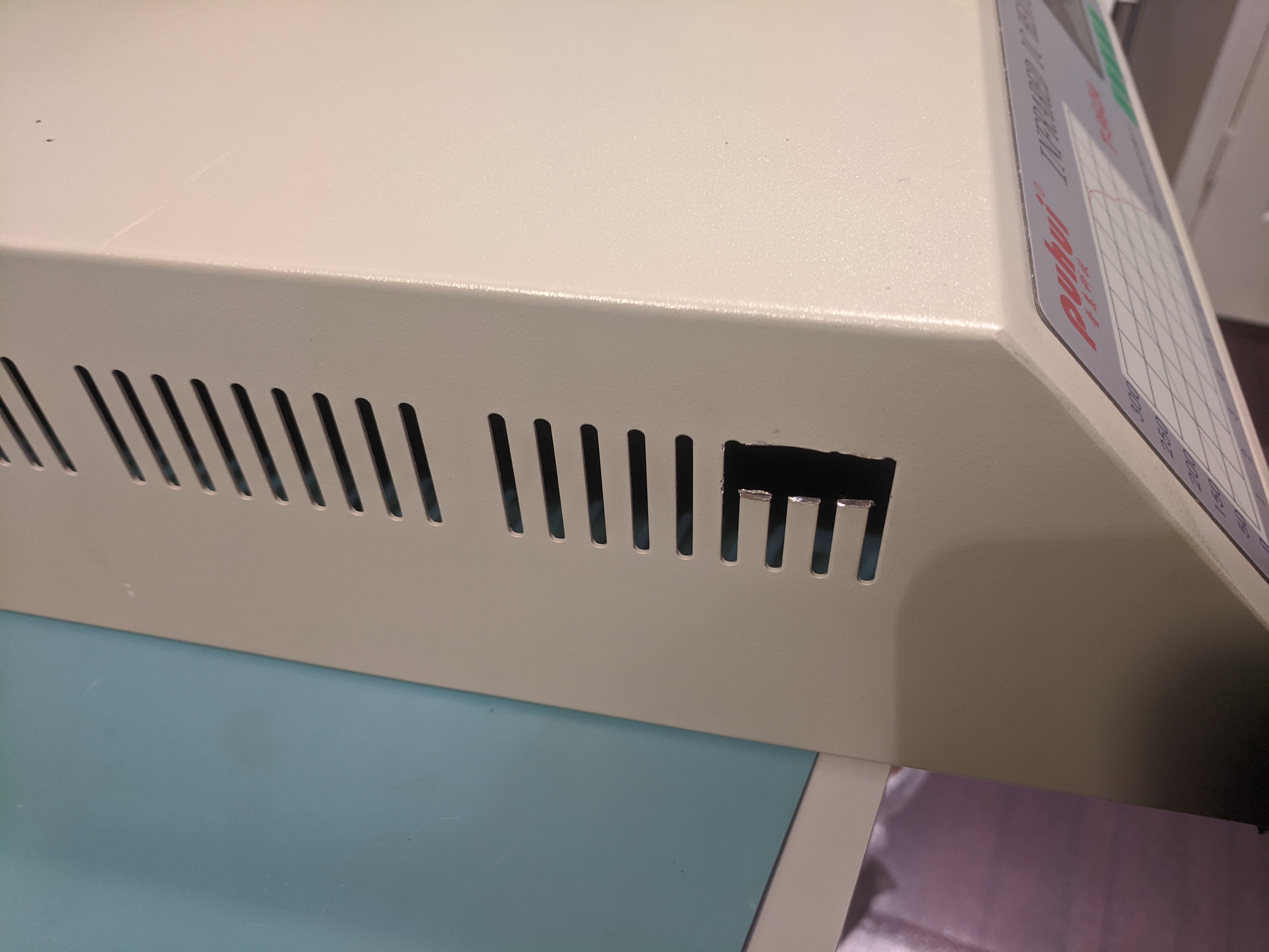
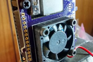
I found two ways to spot the newer version. The text listed it as “2020 New version" and the exhaust port in the back is also different.
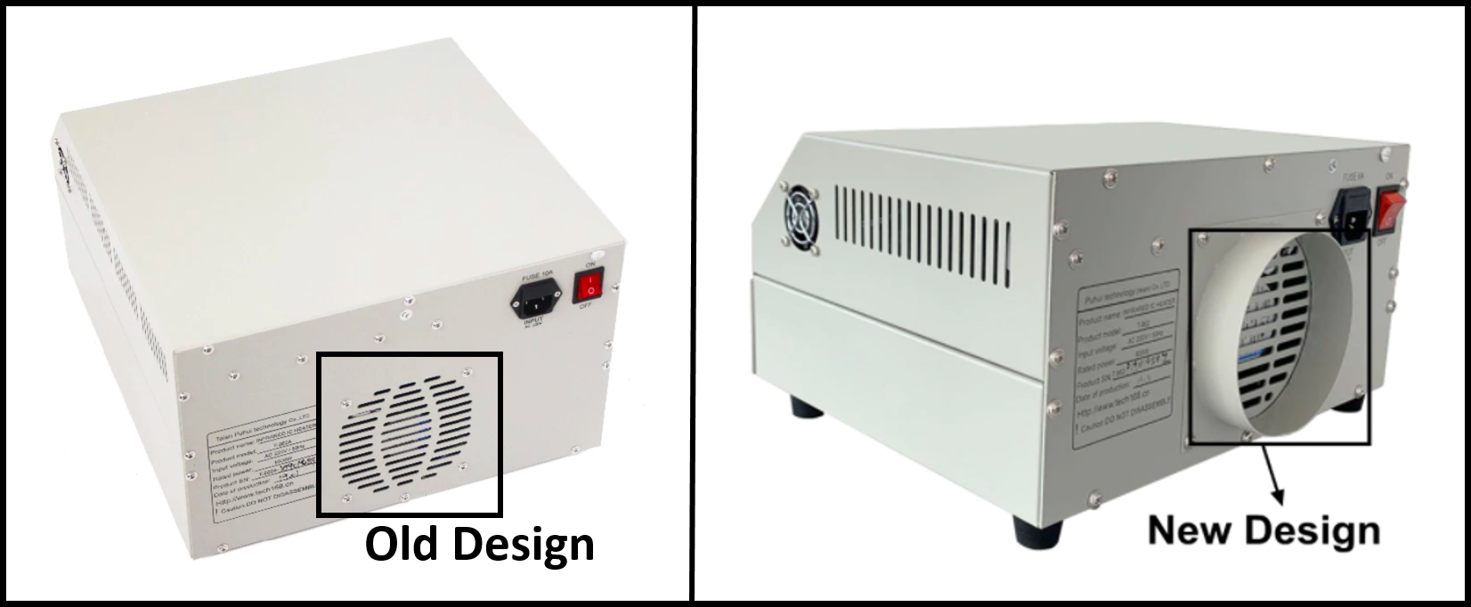
A link to what I purchased can be found in the Links section.
Sources
There are many good sources of information available on these ovens. I narrowed the list down to what I believe are the three critical ones that anyone wanting to modify these ovens should consult. An overview is given here and the links can be found in the page Links section.
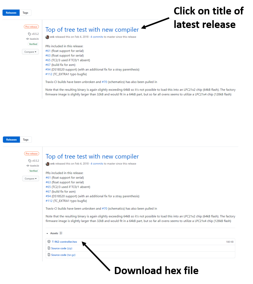
Unified Engineering Github Page
Unified Engineering created new firmware for the ovens. The Github page contains the source code and binaries as well as instructions and notes on other modifications that have been reported helpful.
Seon, The Unexpected Maker
On Seon's YouTube he has a series of three videos on his T-962A. The videos have some useful checks and modifications not on the Github page. It is also very useful to see him step through things like upgrading his firmware. The videos make a nice companion to the written steps on the Github page.
Jerry Walker's Investigation Series
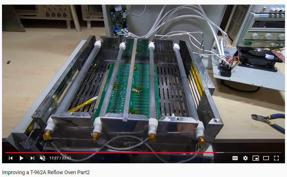
On Jerry Walker's YouTube channel he does an entire series on his investigations on the performance of his oven. He is exquisitely detailed in his investigations. He uses professional-grade equipment to monitor the temperature distribution across the over during the entire heating cycle. He considers several different techniques for improving the performance. Each technique is tested for its benefit or lack thereof and then refined.
Modifications Considered
After reviewing a fair amount of the available information, the following list of modifications was considered the most important. If the analysis of the modification concluded that the modification would be done, there is more information related to the implementation below in the Implementations section.
Grounding
Several owners reported that these machines are not grounded or not grounded well. This is a potential safety hazard.
Analysis result: Recommend you check the grounding.
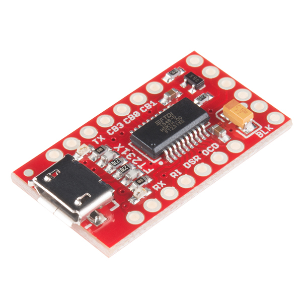
New Firmware
This modification results in a better user experience. The user interface is cleaner and easier to use. But, importantly, it added the ability to take advantage of the cold junction compensation. This modification is fairly easy to do. It is well documented in both writing and video.
Analysis result: Recommend doing.
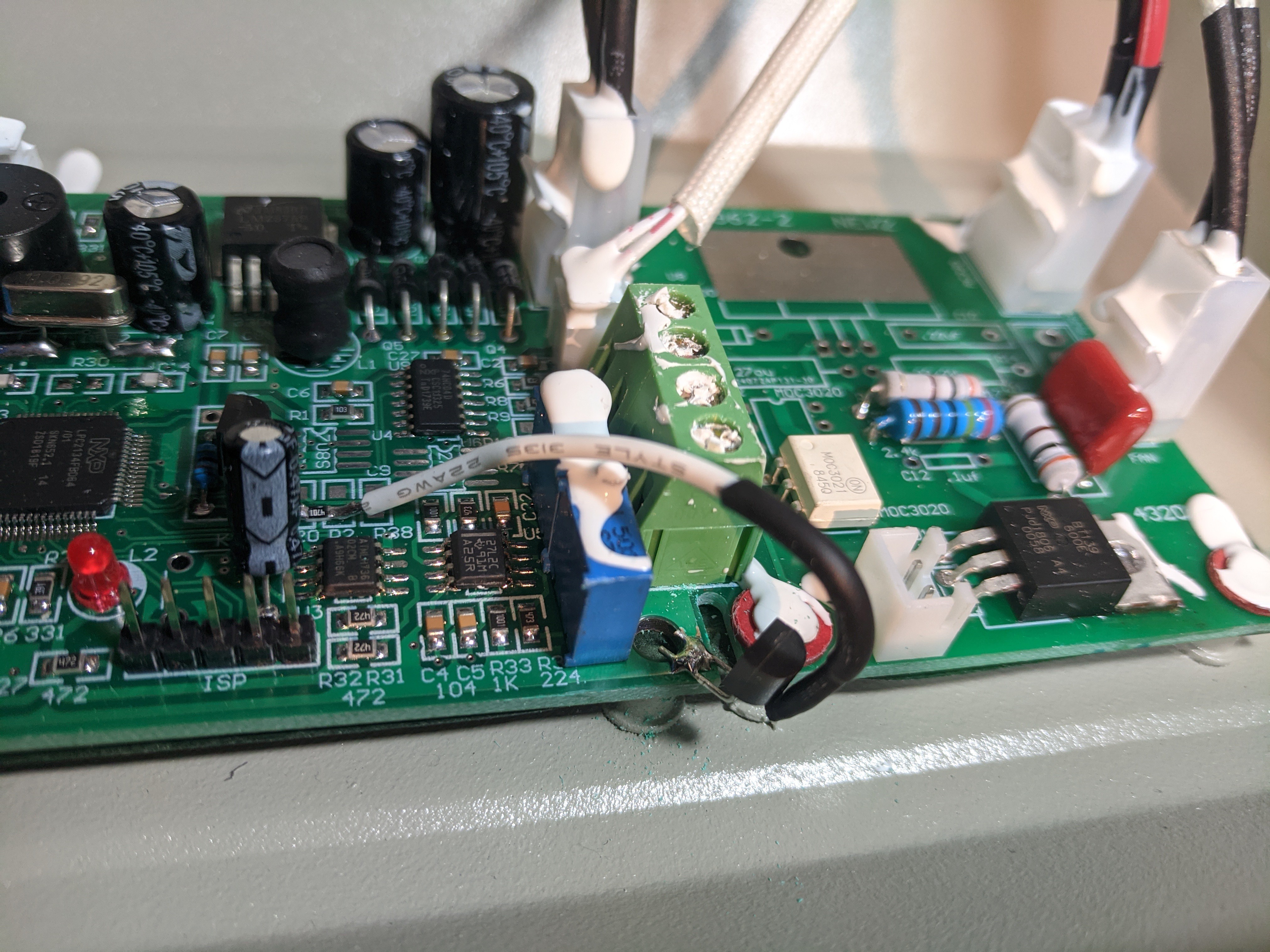
Cold Junction Compensation
This modification lets the firmware adjust the temperature readings for the local conditions and makes the readings more accurate. It is fairly easy to do. It just requires a little soldering. The firmware must be...
Read more »


 Chris Slothouber
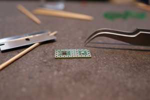
 Sina Roughani
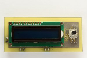
 Aleksander Kawęczyński
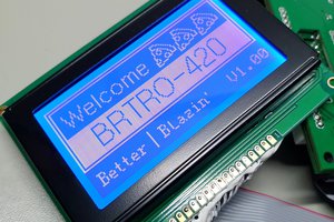
 Blecky