Close
0%
0%

RunTinyRun

Tiny, solar-powered gaming console driven by an ATtiny10 with a firmware of just 780 bytes.

Similar projects worth following
RunTiny is a solar-powered game console hosting an endless runner game written from scratch in assembly to fit into an ATtiny10.
The game only uses the ATtiny10, a 128x32 OLED and a push-button. The firmware - including game mechanics, graphics, I/O - is only 780 bytes.

Why using an ATtiny10? Having little resources forces you to use them effectively, find creative ways to solve problems and learn more in the process.

The game lives on a keychain-sized PCB of just 33 by 25 mm. No one would like to recharge a keychain or waste batteries: so I added a solar panel to play for free, forever!

RunTiny it's entirely solar-powered; a step-up regulator boosts the voltage from the solar cell and charges a supercapacitor. The energy stored is enough to play for approximately 30 seconds and with little direct light, you can play indefinitely.

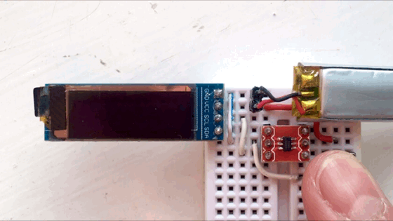
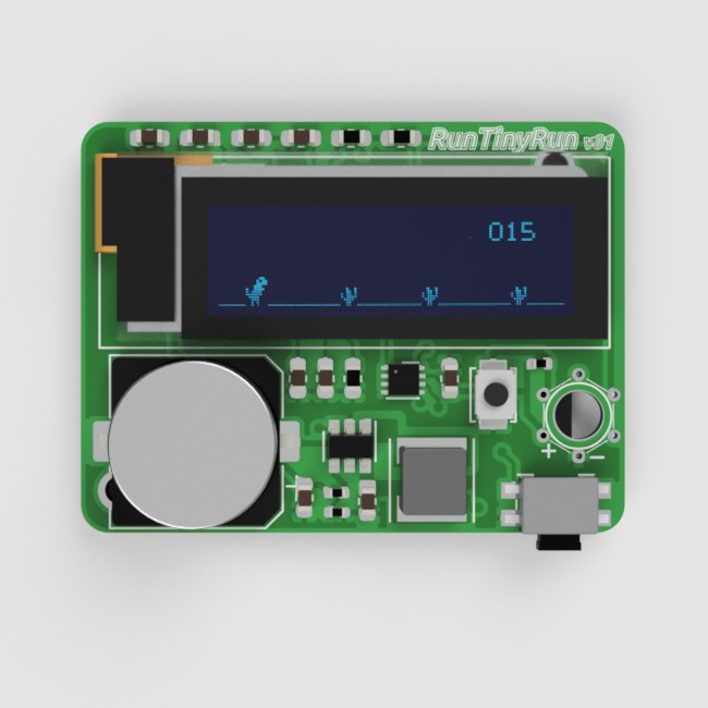
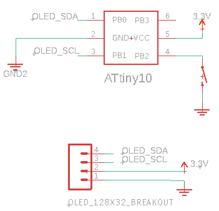
I've been curious for a long time about the mighty ATtiny10 and what can do such a small device. First I had to figure out how to program it through the TPI interface (details here). Then I  tried to drive an OLED display with a bit-banged TWI (also details in this post). Having obtained a good result, I thought to push it further. And what's better than fit a game into 1kb flash memory?
Having played around for a bit, I realized that C would not work for this: the compiled code was taking too much space. Therefore I learned the Assembly basics and I started mixing it with C (I wrote some tips here).
I ended up writing the entire code in Assembly. 
I posted the code on GitHub and I tried to comment every line as clearly as possible.

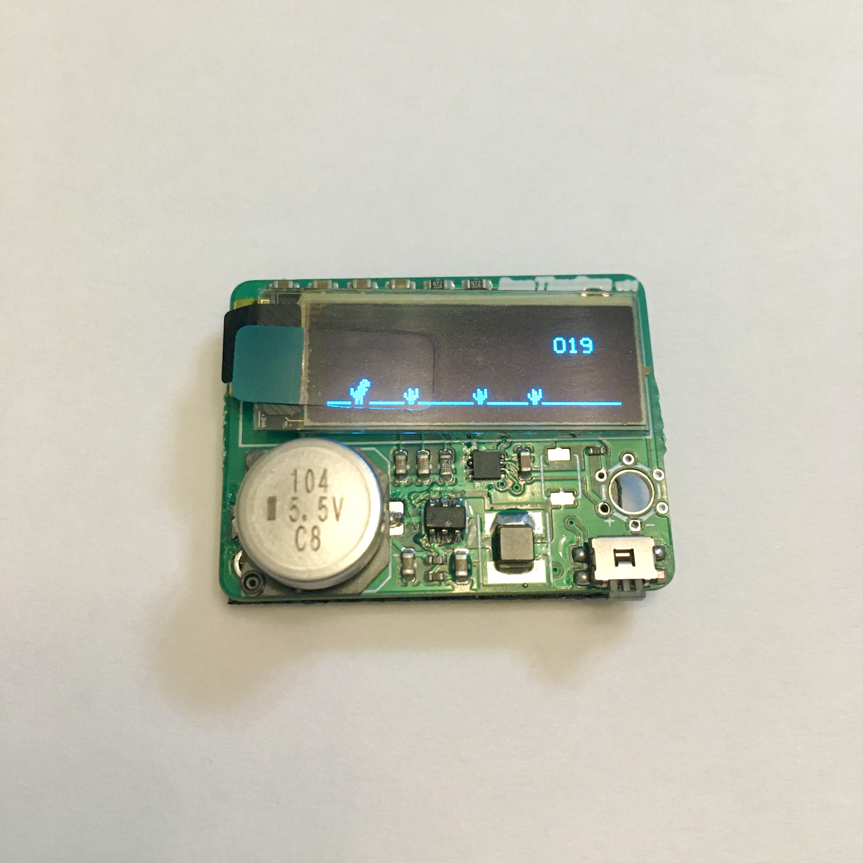
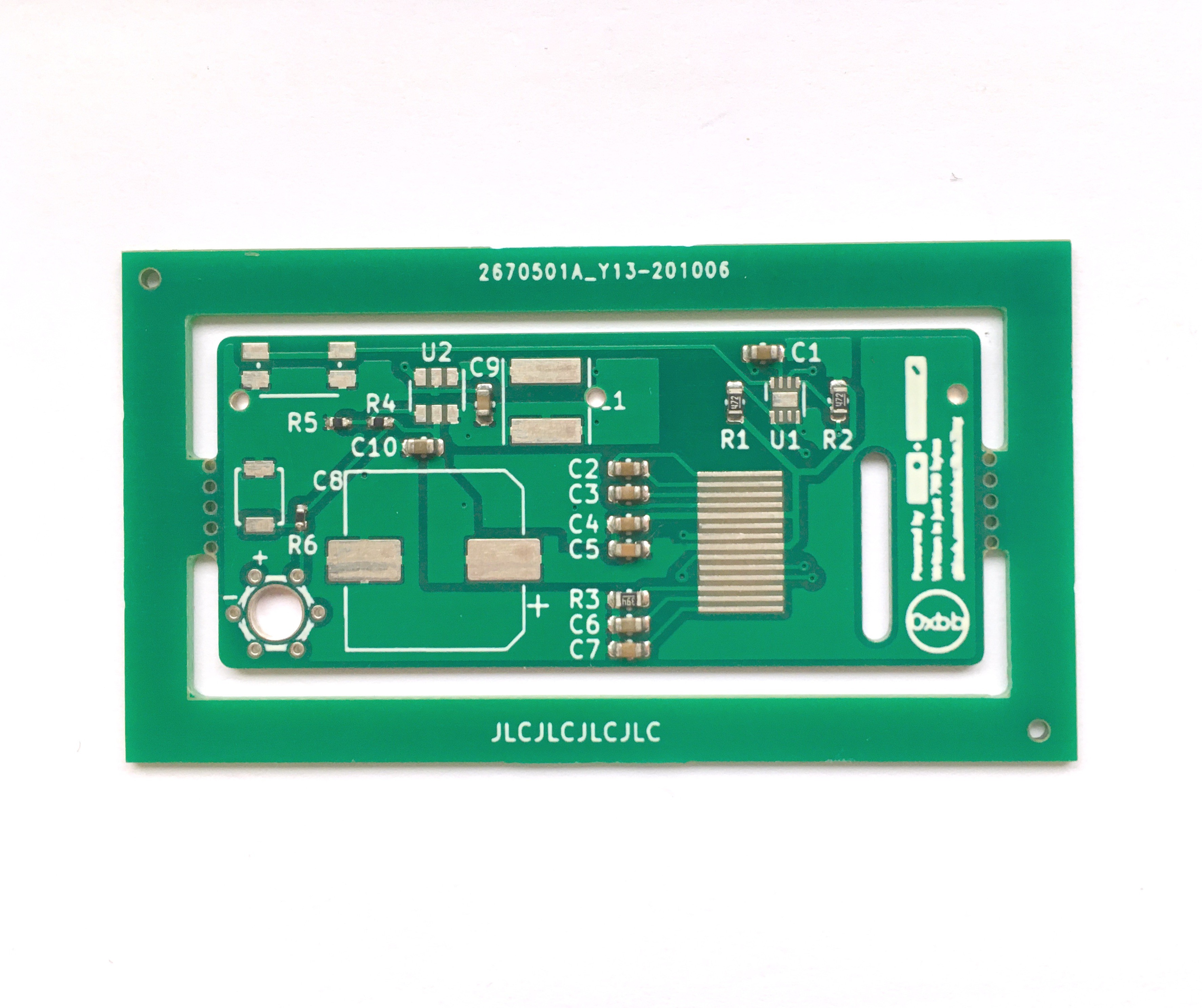
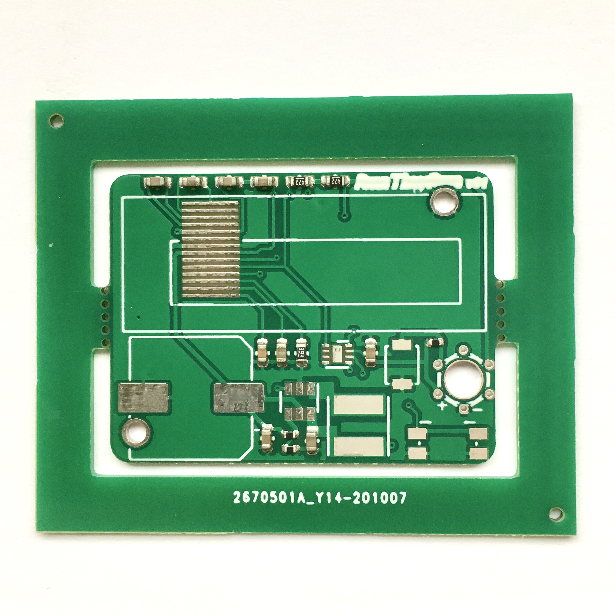
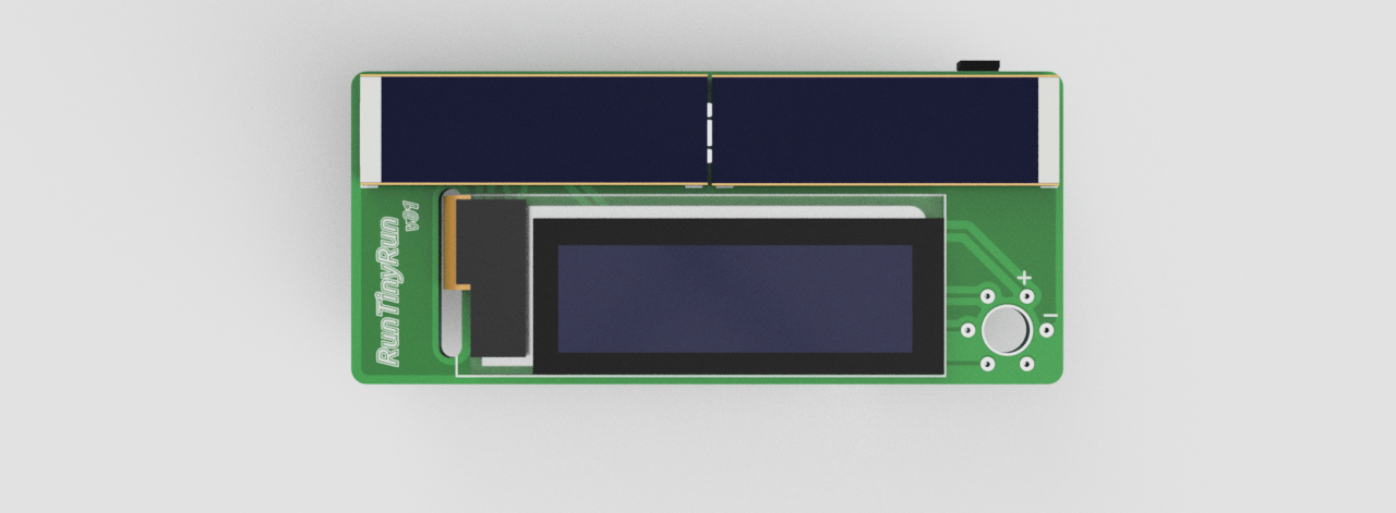
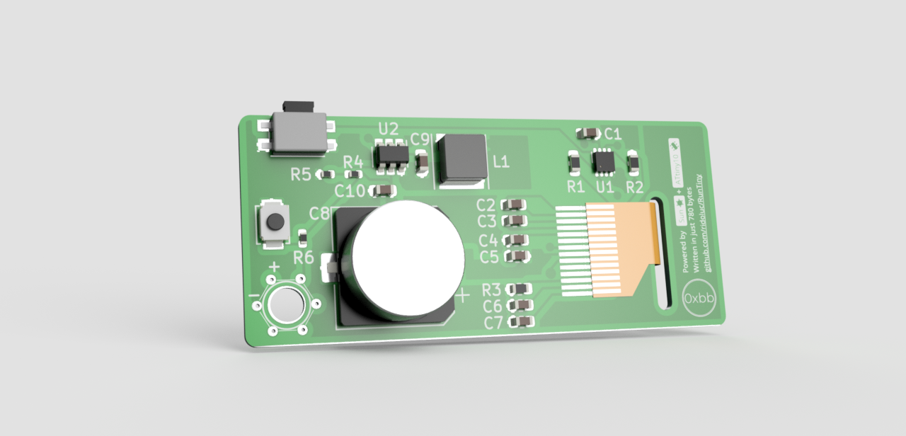
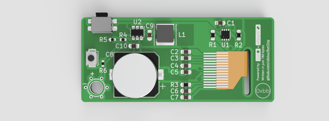
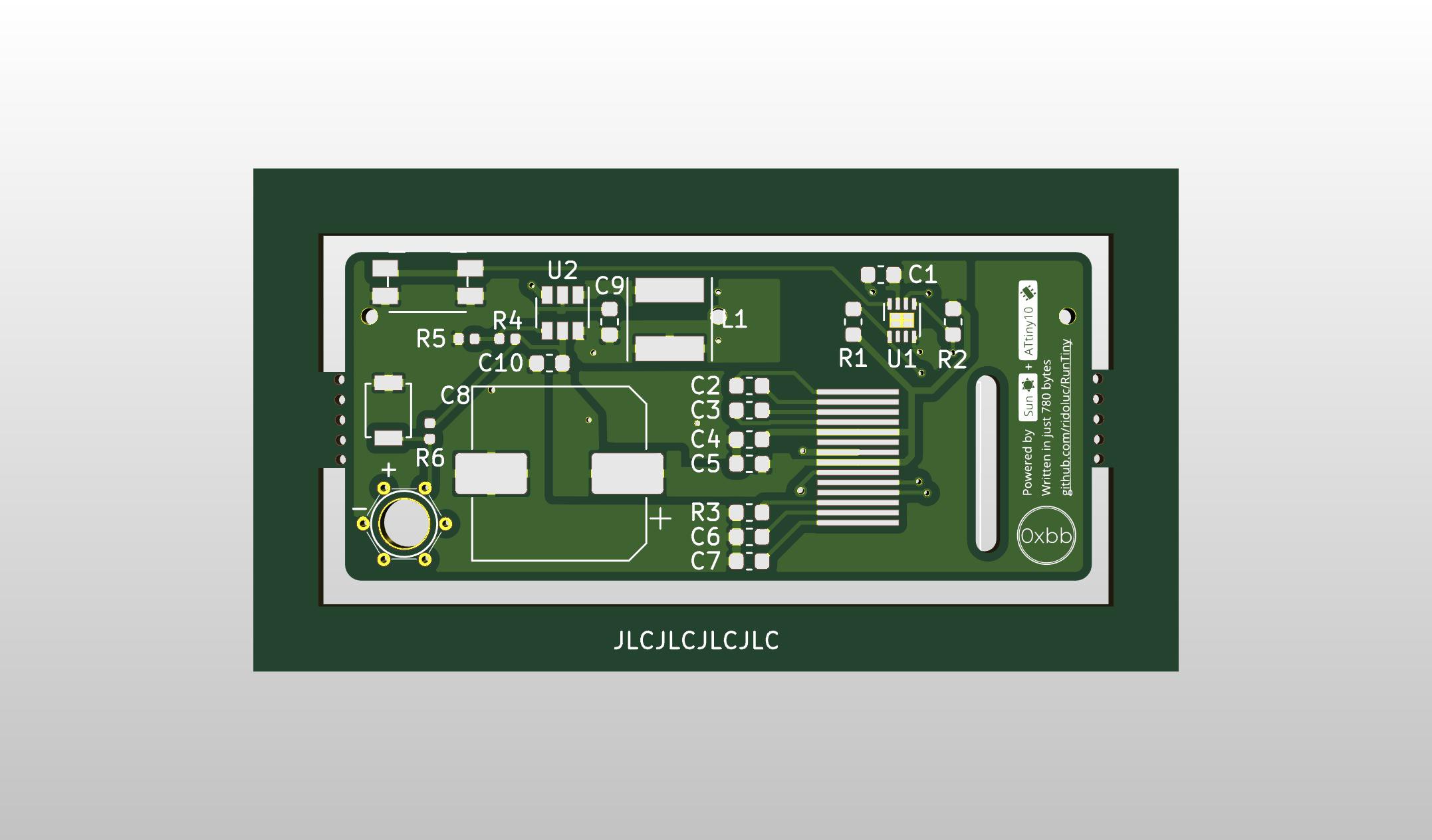
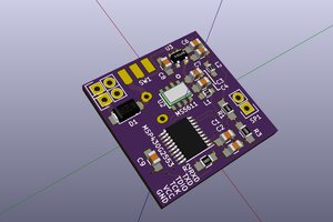
After having spent quite some time coding it, I thought was the case to design a proper PCB. I designed it to be as small as possible: this is going to be a keychain!
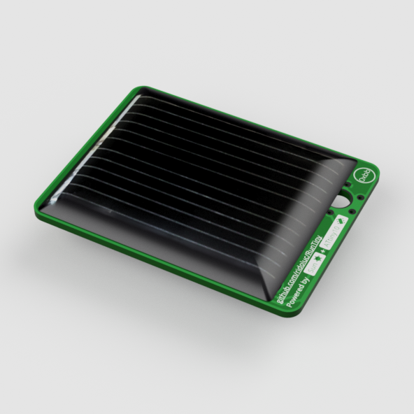
Now, there's a problem: after the phone, the laptop and the watch, I  don't want to charge the keychain too. 
So I need an alternative power source.
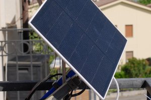
The only feasible energy source is solar even if it's a challenge to extract enough power from such a small surface.
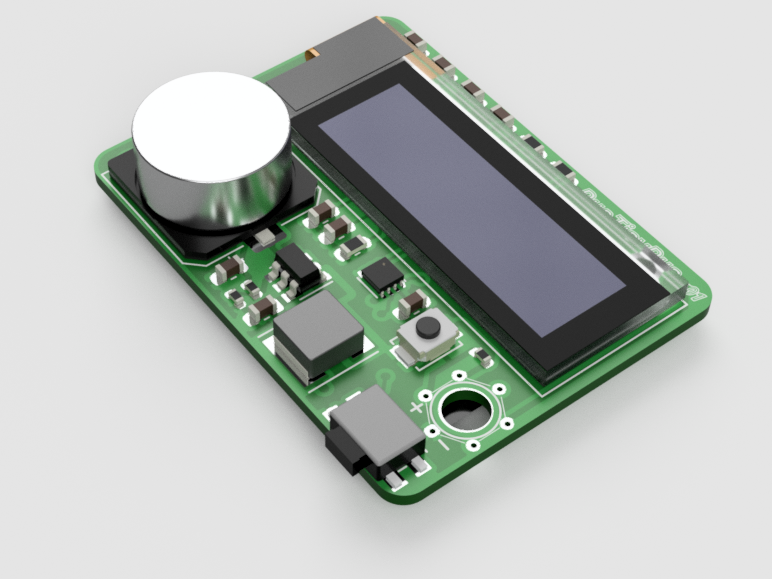
I did some prototyping and the simplest, cheapest solution I found is to boost the voltage from the photovoltaic cells using an MCP1640. The output voltage is used to charge a supercapacitor of 0.1F or 0.22F that acts as a buffer (more details in the log).
The booster is set to output 3.5V and the game keeps working until the supercapacitor is discharged to 1.8V. The 0.22F discharges in about 30 seconds.
This is enough time to enjoy some rounds.
The idea is that you will leave the keychain at the sun for some time (a minute or two) and then play for a while. What if there is no sun, you ask? 
Well, there is no game... but this is implied by being "solar-powered" (actually it can be powered using the TPI port).

RunTiny.pdf

circuit schematics

Adobe Portable Document Format - 31.74 kB - 10/04/2020 at 12:00

Preview
Download

  • 1 × Atmel ATtiny10 AVR MCU
  • 1 × OLED Display 128x32
  • 1 × Pushbutton

  • Epoxy coating failure

    ridoluc03/15/2021 at 09:56 0 comments

    I finally managed to try coating the PCB with epoxy resin. I wanted the circuit to be visible and, at the same time, protected so I thought epoxy would be a good idea.

    The test wasn't a great success.
    First of all, I expected a shiny smooth over but ended up being rough and not visually appetible. This is probably the result of my little experience handling the epoxy.  
    And I also lost the button in the process. Despite paying attention not to cover the push-button, the resin still managed to sneak in, making it unusable. I had to remove it and fix it.

    However, the coating adds some weight and gives a nice solid feeling. I will try again and maybe with a different material. If someone has any suggestion I'll be happy to know it.

  • Boards are complete

    ridoluc11/08/2020 at 21:56 4 comments

    The components are all soldered and the boards are ready. 
    I first soldered all the smaller components leaving display, supercapacitor and solar panels for later. For these, I used solder paste and a hot surface.
    Then I programmed the ATtiny10. This way, if the chip was not correctly soldered I could reflow it without removing other components.
    As always happen when I successfully solder DFN packages, I've been surprised to see the program being uploaded correctly.
    Next, I soldered the display. This seemed daunting at first but ended up being not really troublesome: just use a little solder and a lot of flux.
    Supercapacitor and solar panels followed.

    I built four boards out of the 10 ordered and all of them work. In the process, I had to throw away a step-up converter: if you solder it reversed you get some magic smoke...
    The only missing part is a reset button but this not strictly necessary. I will add it later.
    As expected, the board with the IXOLAR panels takes longer to charge the capacitor. 
    The one with the larger panel can run an indefinite time when directly exposed to sunlight.
    I also found out that a 10uH inductor helps lowering the boost converter start-up voltage.
    In future, I'm going to replace the MCP1640 with an IC specific for solar energy harvesting. Another improvement will be replacing the pushbutton with a capacitive pad and dedicated IC

  • Boards Arrived

    ridoluc10/27/2020 at 09:22 0 comments

    The PCBs have arrived. I'm not impressed with the quality but hopefully they'll work.

    Lesson learned No.1: check the minimum silkscreen specifics of the fab house. I did at some point but, changes after changes, I ended up with characters smaller than the minimum requirement. As a result, the silkscreen in unreadable.
    The mousebites worked well. These could also be smaller as they seem quite strong.
    The soldered components look good. I'm glad I spent a few bucks more to have these assembled. The 0603 package is so small I doubt I would enjoy soldering by hand.
    No worries though, there is plenty of other small things to solder. This on the next log. 

  • Alternative PCB Layout

    ridoluc10/16/2020 at 21:41 0 comments

    I like the first form factor of RunTiny and its design. However, I spent some time trying different options. 

    I came up with an even more compact solution that has all the electric components on the front and the solar panel on the back. 

    The size is 34x25 mm.

    This version is using a cheaper PV cell (about $35c vs $2 of the IXOLAR solution). 

    Since this cell has a larger surface and produces higher current, it also charges the supercapacitor faster and works in lower light conditions. 

    I just need to make the order and I'll see which one looks better. 
    The PCB will be manufactured with the same frame as shown for the earlier version. 

    Here some renderings.

  • PCB Design. Done.

    ridoluc10/11/2020 at 16:09 0 comments

    The PCB design is ready. I tried several options, moving the large components all over the place in the quest of keeping the device as small as possible. It would have been nice to fit more solar panels but two should do the job nicely as anticipated by the breadboard prototype. 

    I placed the OLED display and the two IXOLAR panels on one side and all the electronics on the other side. 
    The OLED connector will pass on the opposite side through a slot. 
    I placed large plated holes on the solar cells pads. These should facilitate the PV cells soldering.
    I designed a circular TPI connector for programming the ATtiny10. This has 6 small plated through-holes placed at the vertices of a hexagon. The distance between these holes is 2.54mm so that I can easily build a connector with pogo-pins.

    The passive components used are mainly in a 0603 package apart from three resistors that are in 0402. I can't bother soldering these components. I will get the passive components assembled from the manufacturer and I will only solder the ICs, solar cells and the display. 

    Here it is a few renders from Fusion360 with the model imported from KiCad (I did some models like the display and the solar panels in Fusion360).

    Front:

    Back:

    The manufacturer is going to place two or three tooling holes on the PCB for the assembly process. The holes should have a diameter slightly larger than 1mm and should not be plated. I really didn't want to have these on the board given the small space available. I thought about panelizing the design but after some research, I was still confused about the process to design the actual panel. Also, the board is too small for a v-cut machine. 

    The solution I found is to create a frame around the PCB and connect this with two handmade mouse-bites. The price will be the same and hopefully it will work as expected.

    This is very simple to do in KiCad: draw two rectangles around the board on the "Edge.Cut" layer. Then connect the frame to the board with two more lines. To remove the outline on the mouse-bites just right click on the Edge layer and select create corner.

    Finally add some non-plated holes. I can't tell the optimal number of the holes or what should be their size.

    I have a lots fo doubts about the solutions I'm using. I guess I will find out if this design works and can be improved once I get the boards.

  • Solar powered circuit

    ridoluc10/04/2020 at 11:59 0 comments

    I decided to build a proper PCB with the smallest size possible. I think it will be nice to carry the game as a keychain. Actually I don't see any other use...

    I want to keep the circuit in view and cover everything with epoxy. I don't want to build a case for it.
    I started evaluating what kind of battery I could use. I need a battery of at least 3V. A replaceable coin battery it's not an option and adding a rechargeable LiPo adds many complications like charging circuit, a connector, under-voltage protection etc...
    So I started thinking about using solar energy. Indeed, it won't be usable at night or on a cloudy day, but it will be the smallest, solar-powered game console! Also, there is no need to charge it and it will have a theoretically infinite lifespan.
    After some research and tests, I found an easy and cheap solution that works. There are also better alternatives, but these add cost and complexity. I may use them for version 2.
    I wrote some simple notes about using solar energy for low power applications here

    The primary project constraint is the size. I want to keep it as small as possible. This is quite a challenge when working with photovoltaic. Obviously, a small solar cell will not be able to directly power the MCU and OLED display. 
    The solution is to have a supercapacitor that acts as an energy buffer: once this is charged will provide the required energy to the system for some time.

    Read more »

View all 6 project logs

  • 1
    Get a programmer

    The ATtiny10 programming uses a protocol called TPI to write the firmware into the flash memory. The cheapest way to program an ATtiny10 is either by Arduino or USBASP. Keep in mind the USBASP needs to have the latest firmware. A tutorial on how to update it is here. A detailed guide to program the ATtiny is here.

  • 2
    Upload the firmware

    You can either get the code and compile it or download the firmware. Both are on GitHub. To upload the code you can use avrdude:

    ./avrdude -e -v -p attiny10 -C ./avrdude.conf -c usbasp -U flash:w:firmware.hex:i -P usb 

     Pay attention to the path of the avrdude configuration file.

  • 3
    Connect the components

    The connections are very simple. Just follow the schematics.

View all 3 instructions

Enjoy this project?

Share

Discussions

Dimitar wrote 03/05/2022 at 22:31 point

Awesome project. I would love one for my keychain. 

  Are you sure? yes | no

Max.K wrote 09/09/2021 at 19:39 point

Really great project! It's intriguing how this works without a fancy mppt chip. Are the IXYS panels enough to power the mcp1640 indoors or is direct sunlight absolutely necessary?

  Are you sure? yes | no

ridoluc wrote 09/10/2021 at 08:25 point

Thanks. I appreciate you like it. I tried to keep it as simple as possible. I already knew that harvesting solar energy with a $7 specialized chip was possible. The challenge was to do it with common components. Indoor light is not enough, it needs direct sunlight. It doesn't need to be strong but artificial light doesn't work.

  Are you sure? yes | no

Max.K wrote 09/10/2021 at 21:13 point

Thanks, that's what I had feared. I did some quick tests with an mcp1640 and a 6x9cm solar cell yesterday and it's still not enough to get a voltage on the output from indoor light. Guess there is a reason these harvesting chips exist.

  Are you sure? yes | no

gabrielk23 wrote 11/01/2020 at 16:19 point

I would buy it if it was on tindie

  Are you sure? yes | no

0miker0 wrote 10/30/2020 at 01:36 point

Please sell this on Tindie. It’s a beautiful project.

  Are you sure? yes | no

ridoluc wrote 10/30/2020 at 15:42 point

Hi. Thanks for the comment!

I'm thinking about it. However it's a very peculiar device that only works with sun. I'm not sure everyone will understand the underlying idea. I can imagine the complaints already… Maybe I can think of other options like selling it as a kit. 

  Are you sure? yes | no

[deleted]

[this comment has been deleted]

ridoluc wrote 10/30/2020 at 15:33 point

The idea is to make it completely independent from any energy source and as simple as possible. Using normal battery was not as challengin as using solar panels :) That is the fun part. With the 0.22F capacitor can run for more than 30 seconds. It's more than enough.

  Are you sure? yes | no

strange.rand wrote 10/22/2020 at 10:14 point

Really cool project.
Currently, I'm working on a solar-powered sensor node that uses a 1-1.5F supercap (can work up to 2 days on it).

Regarding low power LCD and backlight, you can use reflective/transflective one, more sun - more contrast. But you are 100% right about price and availability... I don't know why it as is, I would gladly try to play with such low power screens.

  Are you sure? yes | no

ridoluc wrote 10/22/2020 at 11:52 point

Glad you like it.

I'll be keen to know more about your project. It sounds interesting. Are you planning to post it on Hackaday? 

I always look around for interesting components. As soon as I find a reasonably priced LCD I will try it. 

  Are you sure? yes | no

Nathan Stanley wrote 10/13/2020 at 01:37 point

This is unbelievably cool! I love the concept of a solar powered game using a supercap, even if it only lasts 30 seconds. I guess ultimately a low power LCD could be the way forward to make it playable for longer, but that would need to be custom I guess. Would be like a solar-powered Game and Watch. But I can totally see this as an awesome little toy to have around - no batteries is a definite plus and we have plenty of sun where I am in Adelaide, Australia so could play on this outside almost year round. I'm keen to see the final build!

  Are you sure? yes | no

ridoluc wrote 10/13/2020 at 08:39 point

Thanks! I really appreciate your comment.

As you say, I considered using a low power LCD screen. The first issue is that these are more expensive and harder to source. Second is that you need one with no backlight otherwise it would use more power than the OLED. I’m worried that sun + no backlight is not ideal. On the other hand, the OLED colour and contrast are awesome (difficult to get on a video though)!

It is also possible that a dedicated energy harvesting IC (more efficient) + low power LCD combination may even work inside so the backlight is not a problem. I will give it a try at some point.

I’m working on an alternative PCB layout I will post soon. Any feedback is appreciated!

I will release all the files when I’m sure everything works so you can build yours if you want.

  Are you sure? yes | no

Similar Projects

Does this project spark your interest?

Become a member to follow this project and never miss any updates