 ridoluc
I decided to build a proper PCB with the smallest size possible. I think it will be nice to carry the game as a keychain. Actually I don't see any other use...
I want to keep the circuit in view and cover everything with epoxy. I don't want to build a case for it.
I started evaluating what kind of battery I could use. I need a battery of at least 3V. A replaceable coin battery it's not an option and adding a rechargeable LiPo adds many complications like charging circuit, a connector, under-voltage protection etc...
So I started thinking about using solar energy. Indeed, it won't be usable at night or on a cloudy day, but it will be the smallest, solar-powered game console! Also, there is no need to charge it and it will have a theoretically infinite lifespan.
After some research and tests, I found an easy and cheap solution that works. There are also better alternatives, but these add cost and complexity. I may use them for version 2.
I wrote some simple notes about using solar energy for low power applications here
The primary project constraint is the size. I want to keep it as small as possible. This is quite a challenge when working with photovoltaic. Obviously, a small solar cell will not be able to directly power the MCU and OLED display.
The solution is to have a supercapacitor that acts as an energy buffer: once this is charged will provide the required energy to the system for some time.
The circuit working voltage is ideally 3.3V. Given the size of the PV cells, it's not possible to have 3.3V and also enough current produced.
The solution here is to have a lower output voltage from the solar cells traded for higher current.
The voltage will be boosted to charge the supercapacitor.
I chose the MCP1640 as boost converter because of its low start-up voltage of about 0.7V.
Once the boost converter is started, it will need an input of just 0.5V to remain active.
I tested the circuit with two IXOLAR KXOB25-04X3F cells in parallel and also PV panel of size 25x30mm bought from a well known Chinese online shop. This is supposed to have an open-circuit voltage of 1V and a short circuit current of 80mA.
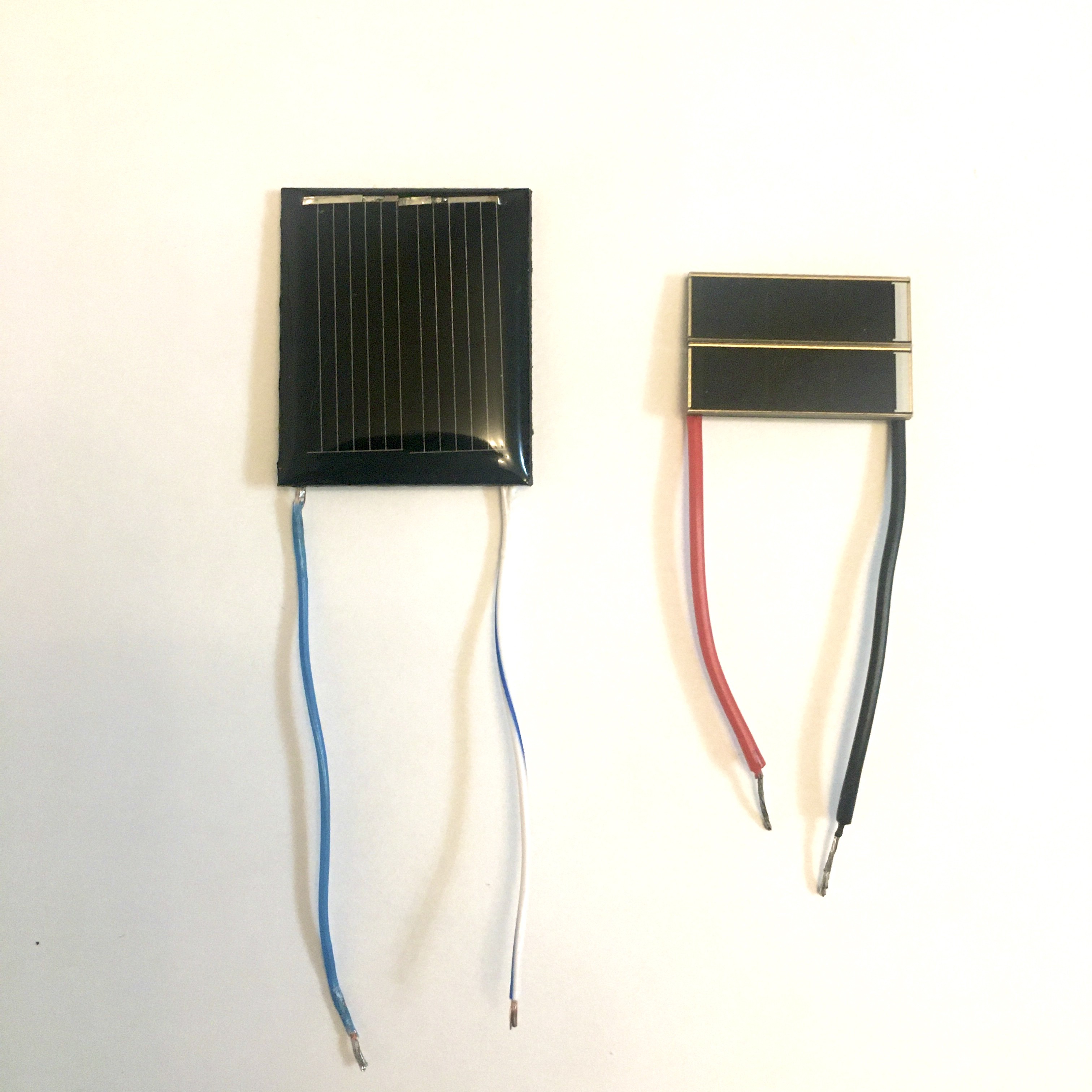
It works with both, but the two IXOLAR cells need better lighting conditions.
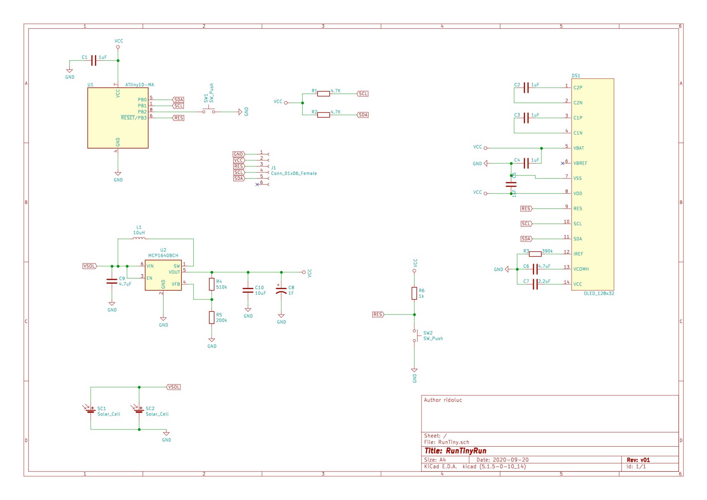
Here the full circuit schematic:
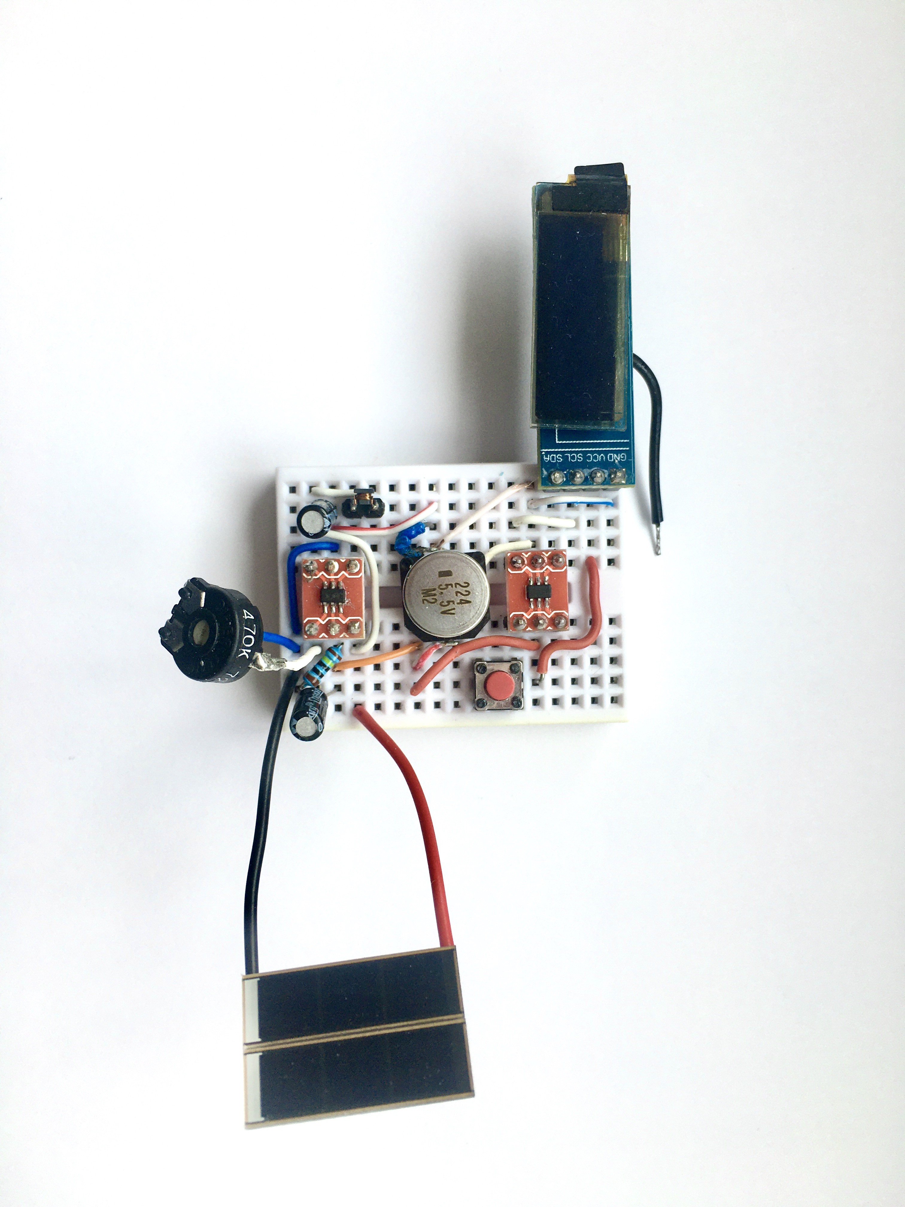
And this is the prototype on a breadboard:
When it's fully discharged, it needs about two-three minutes to charge. The supercapacitor charge will last for 20-30 seconds that are more than enough for some games. It stops working (actually the image will fade away) at about 1.9V. From here, the charging is much quicker because the MCP1640 is already active.
In any case, a strong direct sunlight is needed.
Any suggestion to improve the circuit are welcome.
Next, PCB design!
Discussions
Become a Hackaday.io Member
Create an account to leave a comment. Already have an account? Log In.