 tonyo
tonyoAfter seeing the PCBite system used in a Hackaday article (I forget which), I was intrigued and after a bit of searching, I found it at Saelig for about US$150:
https://www.saelig.com/product/4015.htm
The Old School PCB holder
Photo 1 shows what I normally use to hold a PCB: a couple of blocks of HDPE with an angled step milled in the edge, connected together with two bamboo skewers (press fit into the fixed block, sliding on the movable block) and a 1/4-20 threaded rod + spring + nut to hold everything together. As it is, it's cheap but light, so I have to use blue-tak to stick it to the workbench. Probing is a pain, and so for longer debugging sessions I usually wind up soldering a bit of wire to a test point and clipping the probe to the wire instead of holding onto the probe. This becomes some kind of weird jedi exercise (I am one with the probe and the probe is one with meee) when trying to extract signals from a 2x2mm package.
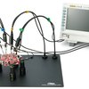
PCBite kit
Photo 2 shows the PCBite kit in action. The large black posts (approx 20mm dia x 55mm tall) are magnetic, they stick to the steel baseplate (approx 200x300mm) and have a plastic base, so it is possible to slide them around on the plate and position them just so. To clamp a board, pull down on the knurled midsection, insert the edge of the board (up to 3mm), and release. A strong spring traps the board between the jaws. If you are concerned about the jaws shorting something out, split-ring self-adhesive isolation pads come in the kit. Just peel and stick them onto the inside part of the jaws.
The probes are screwed onto a gooseneck armature with a magnetic base, and color-coded cable management grommets allow you to identify each probe. Oddly, the BNC connector has a color ring too, but the only color provided is yellow. A small screwdriver-like tool is included to adjust the probe compensation (there is an adjustment hole on the body of the probe's BNC connector as well as an instruction booklet in the kit).
The business end of the probe is a tiny PC board with spring-loaded, gold-plated needle that is quite sharp; it has no problem digging into soft solder pads and staying put. A spare pin is provided for each probe. It appears to be a yank-and-replace procedure, but I did not try replacing the probe.
The probe also comes with a 100mm lead and tiny grabber for grounding the head of the probe.
Using the kit
Fixing the PCB to the kit is a breeze; just pull down on the knurled part of the post to reveal the jaw, stick the PCB into the jaw (it will swallow up to about 3mm of board, and the jaw opens to 6mm or so) and release. Then plop the post onto the steel baseplate and add the other posts as needed.
The probes are then stuck to the baseplate and moved into position. Here is where I think the kit could be improved: the gooseneck armature is a bit too floppy, and tends to fall over due to gravity and the weight of the probe and cable. It seems the only way to make reliable contact is to arch the probe *just so*, and then gently guide the needle to its destination. If the probe stays, whoohoo, if not, move the gooseneck and try again. As the approach angle gets too far from vertical, the risk of floppage increases.
I also tested out the kit with a video microscope, see the photos. I cut a 100x200mm sheet of 0.3mm steel, deburred it, and stuck it to the stage with a bit of double-sticky tape. This makes probing a 2x2mm package much easier than a conventional scope probe. A second set of low-profile jaws would make it easier to see more of the jaws, as the 55mm height places the PCB a little too close to the lens to get a broader view of the board.
Summary
The PCBite kit is a real help on the bench, and I expect it will pay for itself quickly; the only drawback is a somewhat weak gooseneck armature that allows the probe to fall over if the probe is inserted into the test point at a low angle (by low angle I mean close to parallel to the PC board).
If I could have some sort of armature that...
Read more »

 mosaicmerc
 Ian Dunn
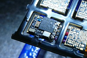
 Christoph
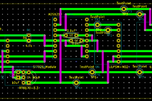
 Mike Teachman
OK, that makes sense, use the entire sheet.
I will have to place the sheet under the microscope as there is not enough room to hold the board and the probes reliably on the microscope stage.