 Mirel Paun
The construction and software files contain the complete information for building the project.
0%
0%
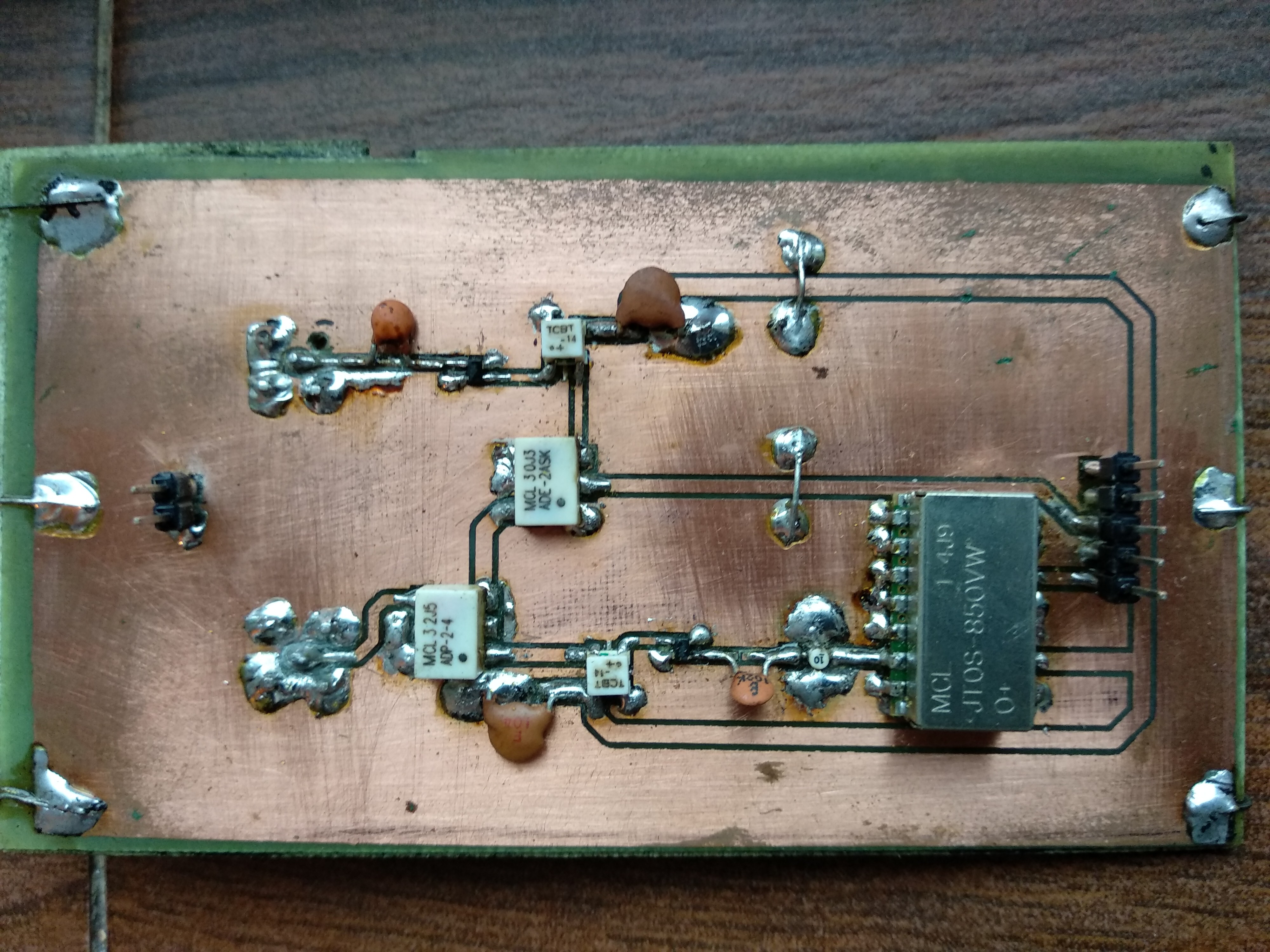
GPRino
Ground Penetrating Radar using Arduino
Become a Hackaday.io member
Already have an account? Log in.
Just one more thing
To make the experience fit your profile, pick a username and tell us what interests you.
Pick an awesome username
hackaday.io/
Your profile's URL: hackaday.io/username. Max 25 alphanumeric characters.
Pick a few interests
Projects that share your interests
People that share your interests


 Embedotronics
 CiferTech
 Ricardo Lima Caratti
Standoff is probably about right. These guys pretty much dominate the market:
https://www.geophysical.com/antennas
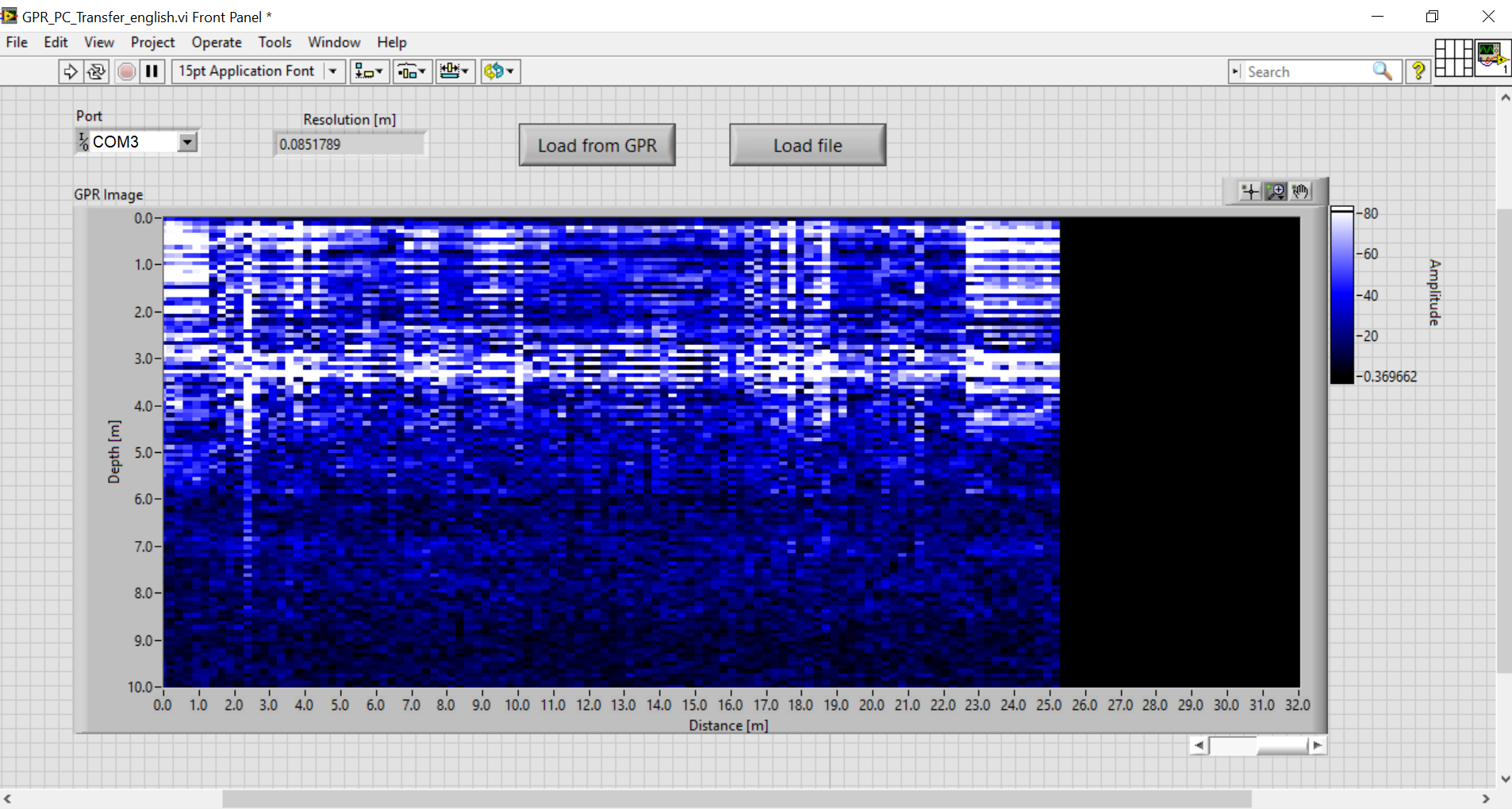
Your horizontal sampling on the bridge is much too coarse. You should be sampling at intervals of a few cm. Bury a piece of steel pipe in sand at a depth of a foot or two, place a board over it so you can roll smoothly across it. Halve the horizontal sample rate until you get a nice looking hyperbola.
For processing the data to suppress noise and form an image I recommend Seismic Unix.
https://github.com/JohnWStockwellJr/SeisUnix
while developed for reflection seismic work it is widely used in GPR research also. I'm a retired seismic research scientist and supported SU professionally for many years. Send me a PM if you want more info.