 fjkraan
Current (v1.2) I.C.-list (actually tested): 4093, 40106, 7400, 7402, 7404, 7405, 7406, 7407, 7408, 7409, 7410, 7411, 7413, 7420, 7421, 7427, 7430,7432, 7433, 7438, 7451, 7486, 74125, 74132, 74138, 74139, 74153, 74240, 74244, 74257, 74365, 74367, 8T97
See: https://github.com/electrickery/logicTester
What the Python script does:
1. find the I.C. definition in the library
2. send the config to the Arduino
3. loop through:
- generate a bit pattern for all the exercise pins
- fill the query-template with the exercise logic levels
- fill the expected result template with exercise logic levels
- calculate the values for the query pins (convert to Python logic expression and evaluate)
- fill the expected result template with query logic levels
- send the query to the Arduino
- retrieve the response from the Arduino
- compare the expected result with the actual result
4. declare result and exit
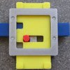
New for version 1.3 are minimal power switching and Arduino only debugging commands. Note that the shown N8T97 is 44 years old and still working.
(The logic probe is an old Elektor design)


 Dimitris Platis
 Lithium ION
 Gregor
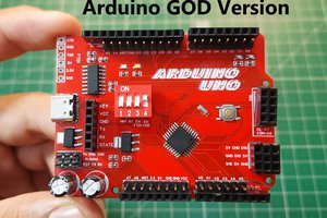
 Sagar 001
Hi, I need to test some (most with up to 48-pin TSSOP) 16-bit TTL / CMOS like 74ABT16245, 74ABT16374, 74ABT163245, 74HC16540, 74HC16541, 74HC16374 and so on. Is it possible to modify or adapt this project for this purpose?
Regards Fernando