Story
There are several old games in which they don't need a lot of complexity, and most of them were played with great intensity by people who had their childhood between the beginning and the end of the '90s.
One of these games is known as rock paper and scissors and uses only the hands of the participants. This game should be played in pairs, with each participant choosing three options: stone, paper, or scissors.
The stone is represented by the closed hand; the role is played by the participant's open hand, and the scissors are indicated by the separation between the index and middle fingers.
The game is developed as the participants interact with choosing one of the options, and according to the rules of the game, each option can lose or win the other.
This is a completely manual game, using only two more participants, however, there is a way to play rock paper and scissors using some electronic devices programmed by Arduino, and Figure 1 illustrates a didactic case developed for this purpose.

Figure 1 - Case of Pedra Papel e Tesoura game.
In the development of this didactic case it was using the Buzzer sound emitter, the LCD display, two indicative LEDs, and eight buttons, you will understand the structure developed.
The developed case was designed with the intention of supporting the Buzzer emitter, which will emit an audible signal according to the use of the keys by each player. In addition to the buzzer, we have an LCD display. He will be responsible for showing the score of the game. Finally, we have buttons that represent stone, paper, and scissors tools.
In this article, you will understand the assembly of the didactic case of the game, as well as know its mechanical structure, fixed by means of the nut bolt set, in its determined fittings.
Therefore, through this article you will learn:
- Know the structure of the didactic case using the Buzzer, the buttons, and the LCD display;
- Analyze the fixation of the mechanical structure of the case by means of screw, nut, and fittings.
- Understand the importance of each part of the case structure for the project as a whole.
- Understand the logic of operation of the Electronic Game Jokenpo.
Now, we will start the complete presentation of the Electronic Game Jokenpo development.
Project Development Methodology
This project consists of presenting a didactic model of a case for the stone-paper and scissors game using the LCD display, the Buzzer sound emitter, and some buttons and other components, as well as the assembly of its mechanical structure.
The project basically consists of the physical structure of the case to support the electronic components, which will process the signal to make the game work.
Figure 2 illustrates the internal region of the game case, as well as the screws responsible for fixing the lateral, front, rear, top, and bottom surfaces.
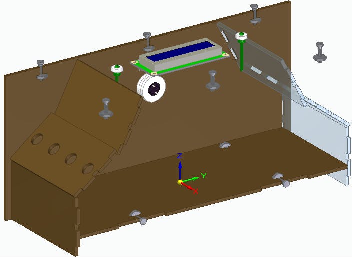
For the fixation of the structure, lateral supports were designed, with fittings dimensioned for M3 nuts and screws.
The support required for the LCD display uses 5 holes. Among them, 4 are used for the screws fixing the LCD itself and the last one will be necessary for your screen to be presented to users.
In addition to these holes, we have the holes for the buttons. They have a 12 mm diameter equally spaced, with 4 buttons for each participant.
Each button group will be at opposite ends of the designed case with a surface greater than the location of the buttons, thus ensuring that opponents do not see your opponent's option.
Figure 3 illustrates the holes for the participants' buttons.

Each participant will have 3 options, between stone, paper, or scissors, and the fourth button will be responsible for confirming the choice. Since the buttons are at opposite ends and covered by surfaces, each participant will not be able to see the opponent's option.
The buttons are arranged in such a way that it will facilitate your choice without difficulty and thus conform the choice, using the instructions on the LCD display.
The game presentation will be transmitted through the LCD display, which will show the instructions that the participants must follow.
It was inserted on the upper surface of the case for a better view of the participants and those watching the dispute. Its structure, as shown in Figure 4

In addition to the visualization available on the display, two indicative LEDs will also be used for the participants.
As participants choose their options and confirm, the LEDs will emit an indicative light.
For the best visualization of the LED indication, they received some indicator rings around them to better highlight them on the upper surfaces of the house.
The rings, or arcs indicating the LEDs, are illustrated in Figure 5.

In addition to the LCD display and the indicative LEDs, a Buzzer audible indicator will also be used.
The Buzzer will emit the signal as the participants interact in the game.
This device was fixed on the left side, where some indicative holes for the sound output were modeled, in addition to fixing rings similar to those of the LEDs.
The fixation of the Buzzer will be done using a specific glue for the case material. Figure 5 illustrates the fixation of the Buzzer in the didactic case.

To fix the front structures, fittings were formed with openings that would be connected laterally.
The front structure of the case has three parts, each of which has two side fittings to be fixed without the presence of screws, as shown in Figure 6.

A total of 10 screws with M3 nuts were used throughout the game structure.
Figure 7 illustrates both the fittings and screws of the case.

The Arduino development board responsible for processing the signal and making comparisons between the players' choices will be placed inside the case.
In the images used, most of the case structures were transparent in order to make internal visualization possible, leaving only some parts with a brown tint, to simulate the wood color used for its construction.
Figure 8 illustrates the entire structure of the game in perspective exploded into a rendered image.

Next, we will present the structure of the Arduino used to build the project.
The JLCPCB wantsto offer 10 units of this Arduino JLCPCB compatible PCB for your projectsfor$2 in your first order with the link:Earn my PCBs Arduino Compatible.

Now, we will introduce the programming logic of the Jokenpo Game.
The operating logic of the Jokenpo Game
The working principle of the Jokenpo game allows each participant to choose one of the three options of stone, paper, or scissors tools. After that, the analysis is made to check which player won based on the chosen tool.
In this game, the user will have 3 buttons and each one will represent the stone, the paper, and the scissors.
After choosing the tool, the user will press the option and then press the Ok button to confirm the choice.
When the option is chosen, the participant's LEDs will light up, to indicate visually that he must wait for the choice of the other player.
After the two participants choose the desired options, the LCD display will send a message to inform who the winning player was.
When the result is defined, the Buzzer will beep and the LED will flash for a few seconds to visually indicate who was the winner of the match.
Conclusion
Therefore, from the development of this project, it was possible to analyze the structure of the Jokenpo Game.
The structure of the game was modeled with M3 fittings and screws for its fixation, to create better mechanical stability.
In addition, all its development was done with the purpose of making it as didactic as possible for its subsequent assembly with the electronic part, because the physical structure of the game case was made by inserts.
In this way, the game was created in such a way as to obey all the rules and with the same experience as the manual game.
If you desire to download the case project files, click in this link.