Close
0%
0%

World's Simplest TTL VGA circuit?

How many TTL ICs do you actually need to output a VGA image?

Similar projects worth following
Inspired by Ben Eater's "World's Worst Video Card" video, I wanted to see how low we could get the chip count, and whether it would fit on a single breadboard. It would have done, if I'd squeezed it in more tightly!

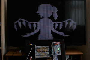
See the YouTube video for more details, where I show the video output and talk through the circuit:

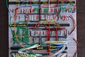
The key simplification from Ben Eater's design is getting rid of all the logic for working out the sync signals and just storing that in the EEPROM instead, along with the image data.  It has some effects on the output resolution options, but is very effective at reducing the chip count, making this a very accessible way to experiment and tinker with video output!

Making your own

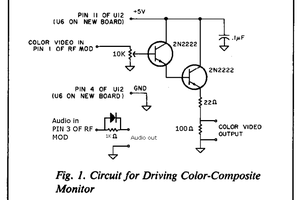
If you want to build this yourself, check out the schematic in the Files section, it's fairly simple.  I've also uploaded two Python scripts there - one that converts the source image into stretched, palettized form; and another that generates the EEPROM image, including timing information and the palettized image from the first script.

Refer to the Build Instructions below for more details.

Extending it

There were a lot of compromises to keep the IC count low, which means that if you want to extend the circuit, without worrying so much about IC count, there's a lot of low-hanging fruit.

  • Things like increased resolution and better colour depth would be fairly easy to achieve using a second EEPROM and/or different timer logic
  • Even higher resolutions could be possible with some shift register magic
  • You could also experiment with a palette look-up EEPROM
  • It should be possible to replace the EEPROM with SRAM and interface it with a CPU - and if you're willing to cut a lot of corners and put up with some glitches, this should be possible without adding many more ICs

If you do build or extend this circuit, I'd love to hear about it, so please let me know!

Hooking up to a Ben Eater-style 6502 computer

I've added some notes in a Project Log below regarding hooking this up to a BE6502 computer.  It's fairly simple and works really well!

vgarom.rom

32K EEPROM image in case you don't want to build it yourself

rom - 32.00 kB - 10/17/2020 at 11:18

Download

genvgarom.py

Script to generate vgarom.rom including timing details, and embedding finch.img from imgencode2.py

x-python - 1.71 kB - 10/17/2020 at 11:18

Download

imgencode2.py

Python script to convert the PNG file into a 5-bit stretched palletized format

plain - 866.00 bytes - 10/17/2020 at 10:38

Download

simplestvga.pdf

Schematic of the circuit

Adobe Portable Document Format - 71.35 kB - 10/17/2020 at 10:10

Preview
Download

  • 1 × 25.175MHz oscillator
  • 1 × 74HC163 Presettable 4-bit counter
  • 2 × 74HC590 8-bit counter
  • 1 × 28C256 32K EEPROM
  • 1 × 74HC273 8-bit D-flipflop

View all 8 components

  • Interfacing with a Ben Eater 6502 computer

    George Foot10/19/2020 at 20:30 0 comments

    Since publishing the original ROM-based version, I've looked into hooking it up to a Ben Eater-compatible 6502 computer.

    This went really well - so I've added the schematics to the project gallery alongside the more compact ROM-based one.  One shows the general setup, the other gives you three choices of clock timing for the CPU.

    There are some demo videos linked below, but first I'll go over the key changes to the circuits...

    Extra components

    The only additional components are three transceivers, a quad 2-input NAND, and a dual D flipflop; and of course the ROM is replaced with RAM.

    BE6502 changes

    The changes you need to make to the BE6502 are:

    1. Disconnect the ROM's ~OE line from ground
    2. Disconnect the CPU's PHI2 input from the existing clock

    Those two things need to be driven by ~ROMOE and PHI2 in the new circuit instead.

    Video circuit changes

    In the video circuit, compared to the ROM version - the ROM is replaced by RAM; the ~OE pins on the counters and RAM are disconnected from GND and joined together and driven by the new timing circuit; and the ~WE pin of the RAM is also driven by the timing circuit instead of being connected to VCC.

    Demo videos

    Here's the first video covering the hook-up:

    And here's the follow-up where I made the CPU clock be driven by the video circuit, to get rid of all the glitches:

View project log

  • 1
    Source an image file

    The Python scripts expect to convert "finch.jpg" so either provide that or edit them to load a different file.  The output resolution is 40x480, so anything higher-resolution than that with 4:3 aspect ratio should be fine.

  • 2
    Run imgconvert2.py

    Next you need to run imgconvert2.py - this converts "finch.jpg" primarily into a "finch.img" binary result.  It also outputs a few PNGs to help debug the palettization process.

    It hard-codes the final video resolution, so if you change that elsewhere in the circuit, you need to change it here too.

  • 3
    Run genvgarom.py

    Then you can run genvgarom.py.  It has some timing parameters, sync polarities, etc defined near the top, in case you want to try a different resolution.  It expects to load "finch.img" and outputs a 32K "vgarom.rom" file.

View all 7 instructions

Enjoy this project?

Share

Discussions

peter wrote 12/16/2020 at 20:32 point

Can you provide the assembler/machinecode for Ben Eaters CPU for running your samples? 

  Are you sure? yes | no

Anton Yarkov wrote 10/29/2020 at 07:13 point

This pixel graphic vga card is really cool! Thinking on potential use as a simple cartoons board for fun and mood with kids! Very nice! 

  Are you sure? yes | no

George Foot wrote 10/31/2020 at 21:49 point

Nice idea 🙂 I think this project is an interesting base for experimentation because there are so many ways to improve it.

  Are you sure? yes | no

Similar Projects

Does this project spark your interest?

Become a member to follow this project and never miss any updates