Brainy.Baboon
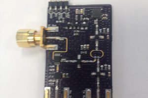
I conceived the idea of λLab to be a really flexible, and at the same time, portable tool that a student or a citizen scientist can build and take out to the field and do on spot assessment of water quality. I also want it to have multiple applications not restricted just to analyzing water quality. I found some inspiration in an instructable by [stoppi] where he uses an Arduino nano. I could identify many flaws with his design that limit is capability which I would try to remove or at least minimize in my design. One thing that is really nice about his design is that it uses the really cheap BPW-34 PIN photodiode to really good effect. That solves a lot of problems regarding cost because photodiodes that are used for scientific purposes are prohibitively expensive and difficult to find.
The main technical difficulties that I would need to overcome can be summarized as :-
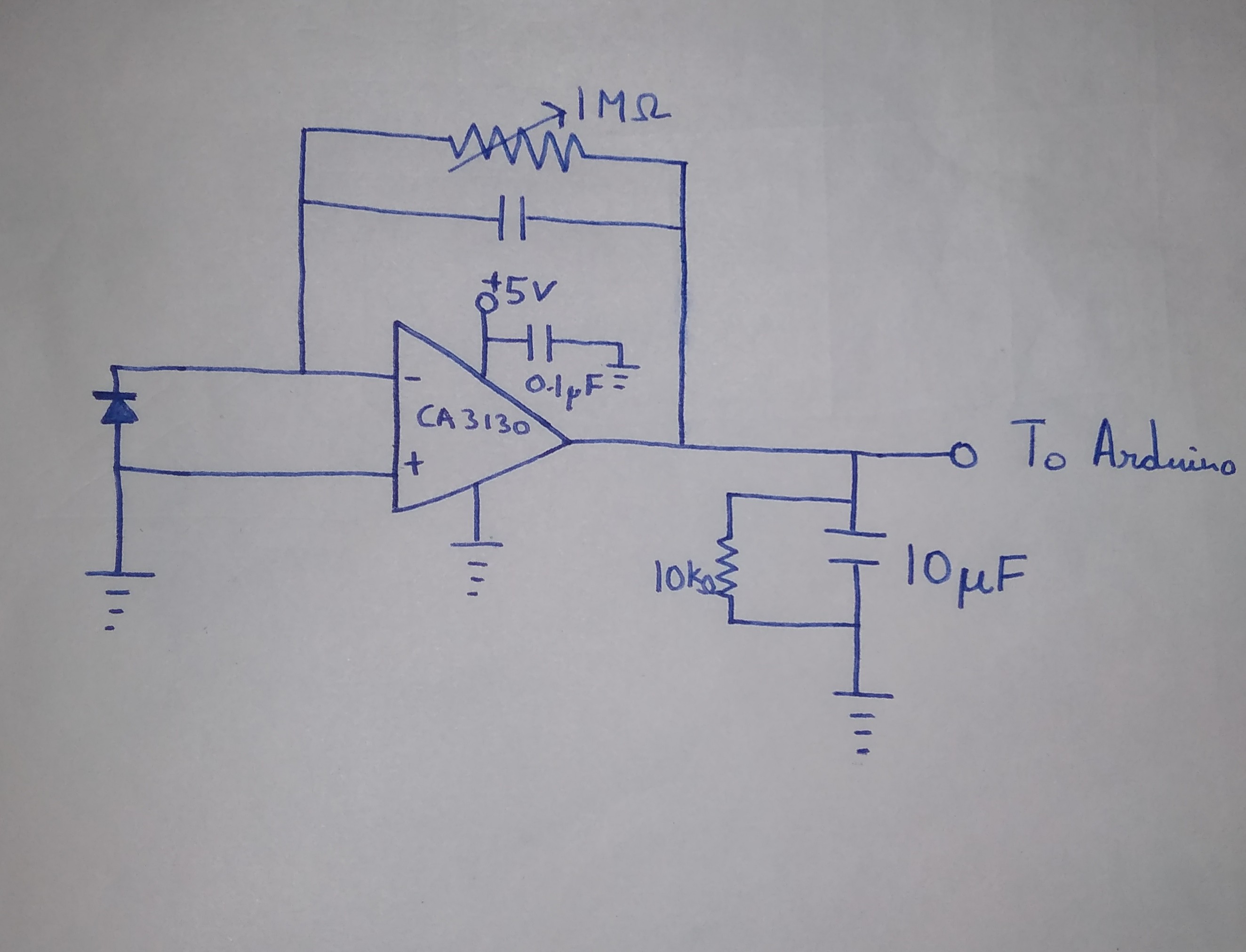
- Designing a low noise, reasonably precise op amp circuit for amplifying the photodiode signal.
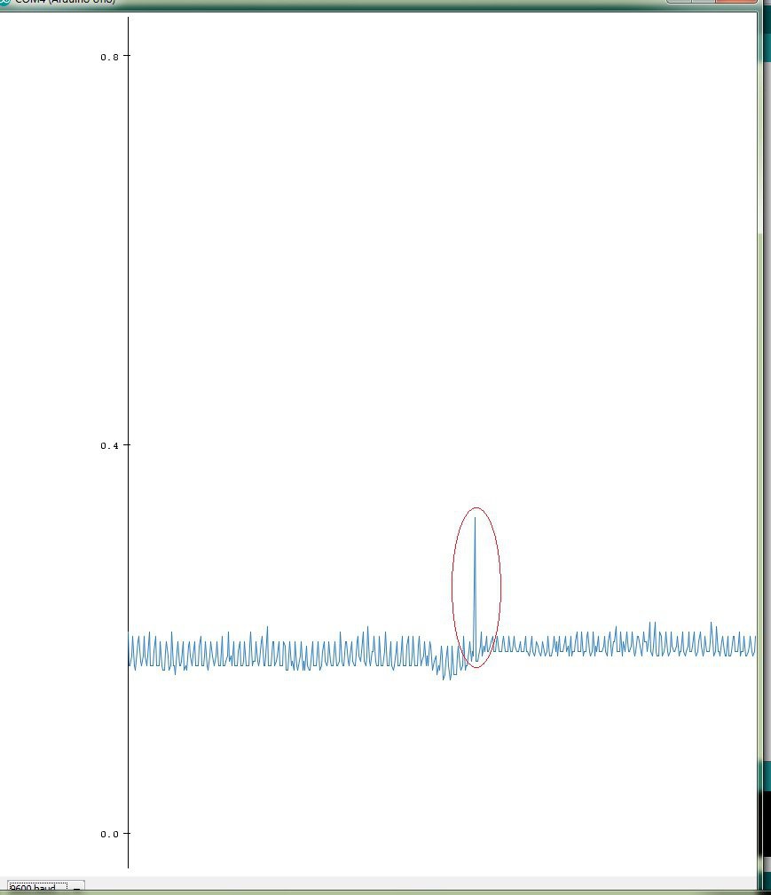
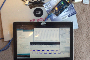
- Minimizing the errors in the in-built ADC of the Arduino.
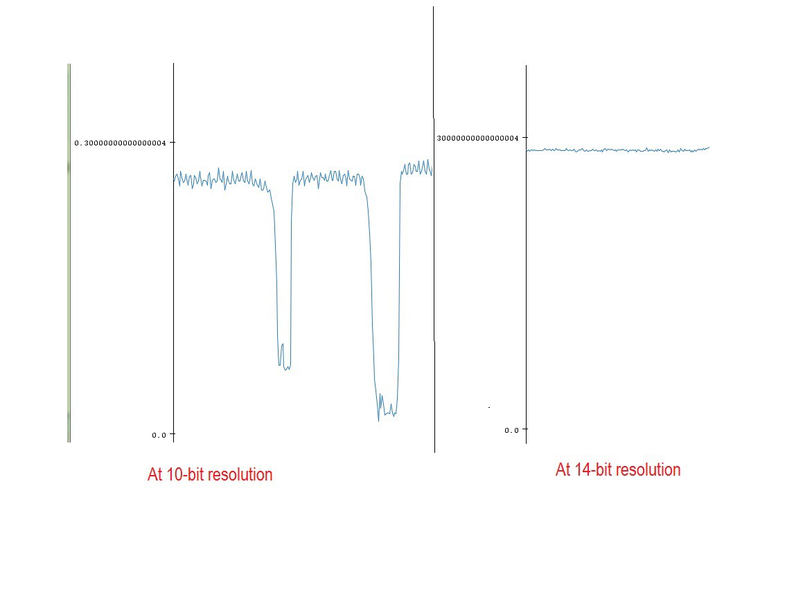
- Maximizing the precision and accuracy of the ADC
- Try and use oversampling to get 2 bits of extra resolution out of our 10 bit ADC without compromising on accuracy and precision.
I haven't figured out all the solutions yet but I would try and learn as I proceed.
 Gintaras Valatka
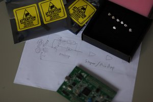
 Justin Scott