parts list:
-----------------------
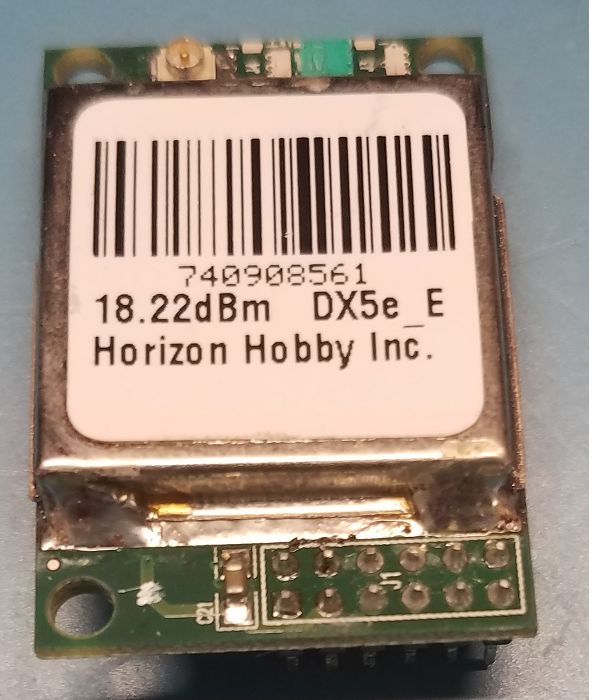
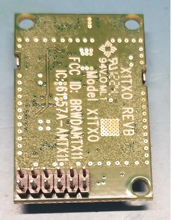
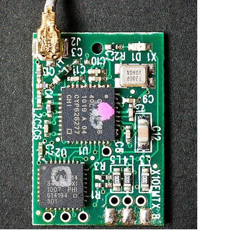
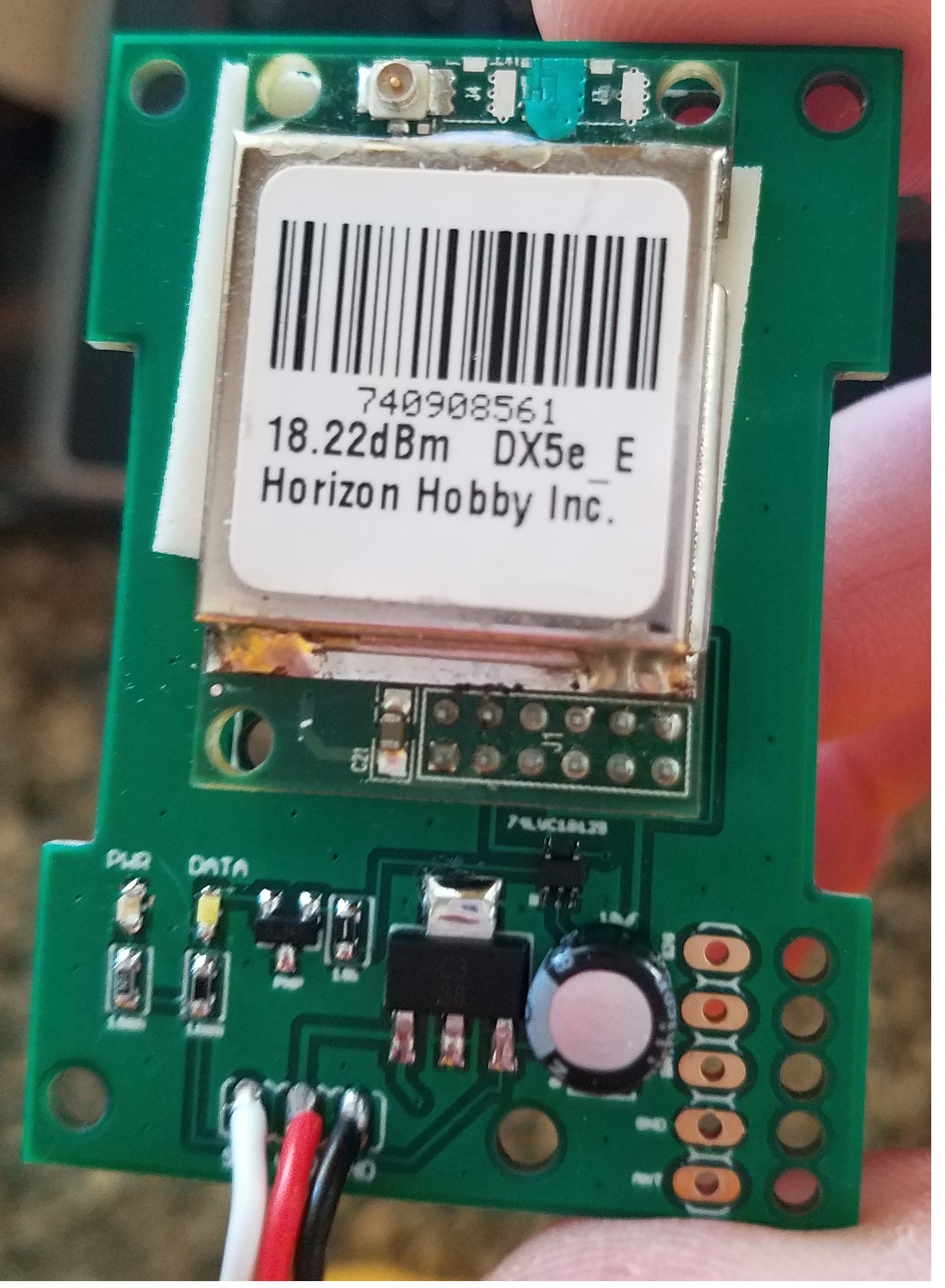
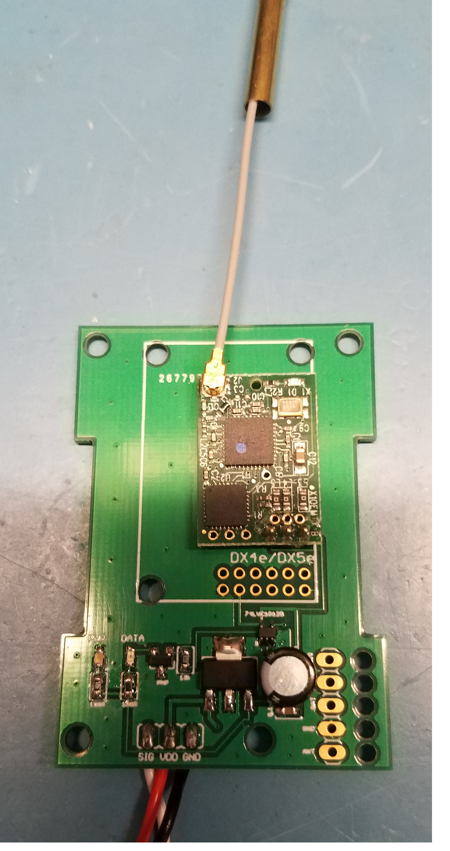
1) OEM DSM/DSMx RF Module (harvest from Genuine DSM radio) ---- qty 1 - approx $40.00
2) PCB (JLCPCB or OshPark) ---- qty 1 - $16.75
3) 74LVC1G125 line driver - digikey: 296-11604-1-ND ---- qty 1 - $0.26
4) UA78M33 3.3v regulator - digikey: 296-13424-1-ND ---- qty 1 - $0.58
5) 200 ohm resistor - digikey: P200HCT-ND ---- qty 10 - $0.32 (per 10)
6) 100 ohm resistor - digikey: P100HCT-ND ---- qty 10 - $0.32 (per 10)
7) 10k ohm resistor - digikey: P10KHCT-ND ---- qty 10 - $0.32 (per 10)
8) 20 ohm resistor - digikey: P20HCT-ND ---- qty 10 - $0.32 (per 10)
9) PNP transistor - digikey: MMBT2907ALT3GOSCT-ND ---- qty 1 - $0.15
10) 0.1uF cer cap - digikey: 478-6206-1-ND ---- qty 1 - $0.24
11) orange led - digikey: 160-1445-1-ND ---- qty 1 - $0.24
12) blue led - digikey: 160-1646-1-ND ...
Read more »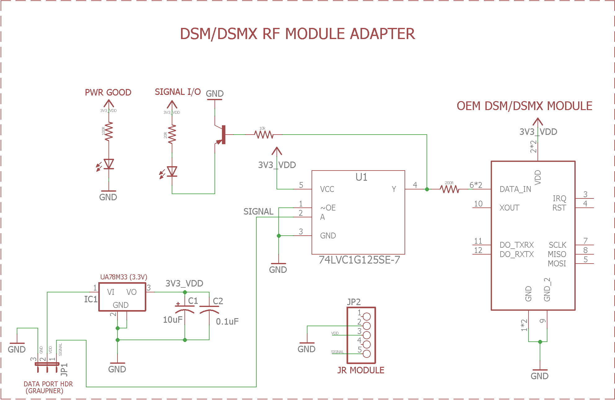

 Hexabitz
 Ruslan
 Hulk
Hulk
Thanks for the credit!!!