 Ken Yap
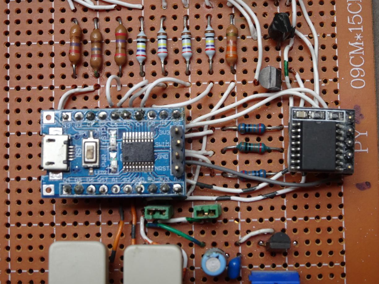
Photo of board with added RTC on right, plugged into 5-pin header.
While it is possible to tune the onboard oscillator to give a semblance of accuracy in timekeeping, this is tedious and only really works for a small temperature range. So I looked into ways of improving the accuracy. A DS3231 based RTC will provide a great improvement at little cost, only a couple of dollars.
Fortunately the B4 (SCL) and B5 (SDA) lines on the STM8 board are still available. I added a 5-pin header to the prototype board and connected 4 lines to the MCU. Vdd goes to the 3.3V supply (actually 5V as it's running at 5V, but the RTC can handle that), GND to GND of course, and SCL to B4 and SDA to B5. A couple of 4k7 pullup resistors to Vdd complete the addition.
I started coding using the I2C routines in the Standard Peripheral Library but discovered that the I2C interface is quite comprehensive and needs a good understanding of the various events in the I2C protocol.
So I coded an alternate implementation to get basic experience with this RTC, using bit-banging with the GPIO routines on the same two pins. I thought it should work first go after a clean compile as the code had been tested before on other processors. However I was over-optimistic as there were a couple of things I didn't anticipate. The first is that I had been spoiled by the 8051 pins which have weak pullup and thus don't have to be explicitly switched between input and output. In places in the protocol, one has to switch the SDA pin to input. The second is that the GPIO_ReadInputPin routine doesn't return 0 or 1, but rather 0 and !0, the difference being anything non-zero qualifies as !0. In particular the routine returns the bit in the SDA position which is B5 or 2^5. So one part of the byte assembly routine has to be changed from
data |= GPIO_ReadInputPin(GPIOB, GPIO_PIN_5);
to
data |= GPIO_ReadInputPin(GPIOB, GPIO_PIN_5) ? 1 : 0;
Being able to observe the program in action using PlatformIO was a great help debugging.
I will get back to coding the native I2C implementation after digesting the I2C section of the STM8L reference manual, which is for the STM8L series but also applies to the STM8S series.
A remark: If you had modified the design to accommodate a more conventional 4 digit display, then the only line left for driving the 4th digit is D1 (SWIM) which means you have to decouple that line for flashing or debugging. Other solutions are to get a STM8 with a larger set of GPIO lines, or to use a decoder or shift register to drive the digits so that you don't need more than 2 or 3 digit outputs.
Discussions
Become a Hackaday.io Member
Create an account to leave a comment. Already have an account? Log In.