 kutluhan_aktar
To obtain temperature, humidity, barometric pressure, and approximate altitude, I used an Adafruit BME280 I2C or SPI Temperature Humidity Pressure Sensor. Below, you can inspect the formulas I implemented to calculate the approximate evaporation rates by temperature and humidity.
To detect the water flow rate and the total water spent, I used a YF-S201 Hall Effect Water Flow Sensor. And, to observe the soil moisture, I used a Soil Moisture Sensor.
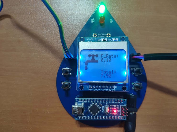
To create an interface to display the mentioned variables, select modes - A. Tem. Eva., B. Hum. Eva., C. Moisture, and D. Usage - I used a Nokia 5110 Screen and pushbuttons (6x6).
Also, I added two indicator LEDs (green and red) to check whether the thresholds given for each mode surpassed or not.
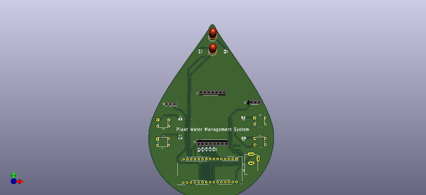
After completing my design on a breadboard and testing the code, I designed a PCB (Plant Water Management System) with a unique water drop shape to create an apt and easy-to-use accessory for houseplants :)
Huge thanks to PCBWay for sponsoring this project by providing PCB, PCBA, and the Adafruit BME280 I2C or SPI Temperature Humidity Pressure Sensor.

Step 1: Designing and Soldering the Plant Water Management System PCB
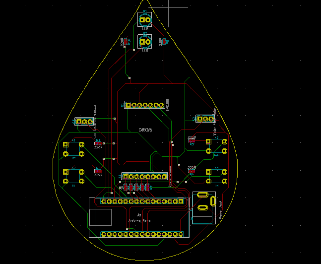
I designed the Plant Water Management System PCB by using KiCad. I attached the Gerber file of the PCB below, so if you want, you can order this PCB from PCBWay to create a stylish and easy-to-use device to track the total water spent while watering houseplants and evaluate approximate evaporation rates by temperature and humidity :) Click here to inspect and order this PCB directly on PCBWay.

PCBWay sent me the board with the Adafruit BME280 sensor, 220Ω resistors, and 1K resistors attached, thus I soldered the remaining components as follows. You can download the BOM file for PCBA below.

First of all, by using a soldering iron, I attached headers (male and female), the power jack, 5mm green LED, 5mm red LED, and pushbuttons (6x6).
Component list on the PCB:
A1 (Headers for Arduino Nano)
S2 (Headers for YF-S201 Water Flow Sensor)
S3 (Headers for Soil Moisture Sensor)
J2 (Headers for Nokia 5110 Screen)
K1, K2, K3, K4 (6x6 Pushbuttons)
D1 (5mm green LED)
D2 (5mm red LED)
J1 (Power Jack)


Step 2: Using the Adafruit BME280 Temperature Humidity Pressure Sensor with Arduino
It is easy to use the Adafruit BME280 sensor with Arduino in its two different modes - I2C and SPI. However, in this project, I used the I2C connections, so the PCB (Plant Water Management System) does not include the switch-back option between I2C and SPI.
To begin reading sensor data, you will need to install the Adafruit_BME280 library (code on Adafruit github repository). It is available from the Arduino library manager.
- From the Arduino IDE, open up the library manager.
- And type in adafruit bme280 to locate the library, then click Install.
- Also, add the Adafruit Unified Sensor library.
- Open up File->Examples->Adafruit_BME280->bmp280test to test the sensor's features.
Below, you can inspect the I2C wiring on Connections.

Step 3: Calculating the discharged volume of water w/ YF-S201 Hall Effect Water Flow Sensor
YF-S201 Hall Effect Water Flow Sensor has an embedded hall effect sensor, and it produces electrical pulses each turn when water flows. The pulse signal generated by the sensor is a square wave, so we can easily convert the pulse to the flow rate with:
Pulse frequency (Hz) / 7.5 = flow rate (L/min)
This formula is derived from the equation below and needs calibration when executing. In my case, I did not encounter more than a discrepancy of 0.15 liters.
Q (flow rate) = V (velocity) x A (area)
To glean the discharged volume of water by seconds, we need to divide the flow rate by 60.
water_spent = flow rate (L/min) / 60
Then, collecting the water_spent variable recursively, we can reach the total volume of water spent:
total_water_spent += water_spent
Below, you can inspect how I code these formulas in...
Read more »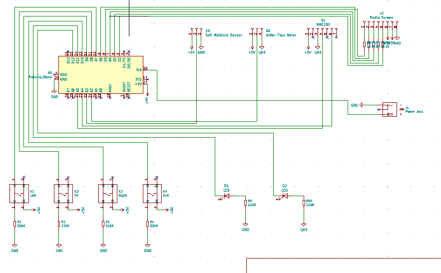

 Lithium ION
 Cedric
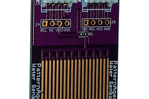
 Pattern Agents
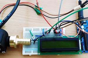
 electronicsworkshops
Please feel free to leave a comment here if you have questions or concerns regarding this project 😃