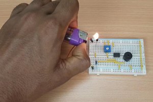
Here's how it works. It's so simple I was astonished at how slow I was at discovering this.
- Make a KiCad project.
- Build a circuit in Eeschema.
- Assign the footprints to the components, making sure to only use
footprints that have pin spacing which are multiples of 2.54mm (common breadboard hole spacing). - Go to Pcbnew and import the netlist.
- Set the grid to 2.54mm (100mils).
- Place and wire up the components, while trying to only use one copper
layer and avoiding chamfered tracks. (other copper layers may be used for wire links that are insulated or on the other side of the board) - Export the circuit as PNG.
- Scan your breadboard.
- Put the circuit on top of the scanned image.
- Print it out. That's it! Now go and replicate what you see on the breadboard.
 Torbjörn Lindholm

 Kelly Heaton
 Sagar 001

Neato. 👍 A couple of tips:
There's a recent plugin which may become standard, that lays out the components in pcbnew in the same relative position as they were in eeschema, instead of the standard packed block of footprints, so starting off is easier. https://forum.kicad.info/t/schematic-positions-to-pcb-positions-plugin/23528
It's not necessary to export a netlist in eeschema to import into pcbnew. You can just use Update PCB or shortcut F8. This is even more useful when you need to update the PCB incrementally, say when you change a component or a footprint.