 Silas Waxter
Introduction/Summary
The lock riser mechanism is used to lift/lower the lock mechanism during attachment and raise the robot of the ground during the lift phase. The rack-and-pinion was used for two reasons: One, my relative familiarity with rack-and-pinion. Two, the existing lock mechanism was designed with the assumption that it would be vertically placed on the lander's handle.
The first version of the mechanism is a "direct drive" system in which herringbone teethed racks and pinions were directly attached to the motors and lock mechanism respectively. The housings for the racks were designed in two pieces to ease 3D-printing (print volume). The base of the housing was attached to the grid plates, which spanned our robot.
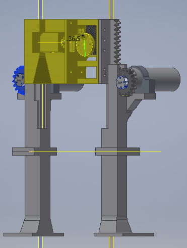
Issues
First, the two motors weren't strong enough to lift the robot. Second, the cutaway material on the upper rack housings (allow lock riser to collapse) was too loose allowing the rack to move in directions other than strictly vertical.
Discussions
Become a Hackaday.io Member
Create an account to leave a comment. Already have an account? Log In.