 strange.rand
Let's start from the beginning. I live in an apartment that faces south and west so I can get reliable temperature measurements from a standard thermometer (you know, such thing on your window with a little bit of colored ethanol inside) only till 1-2 PM. That's why I decided to start this project.
The initial idea was to keep it simple and cheap. Components:
- ATmega328P microcontroller
- RFM69 transceiver
- HTU21 temperature and humidity sensor
- 1F 5.5V supercapacitor
- Some solar panel
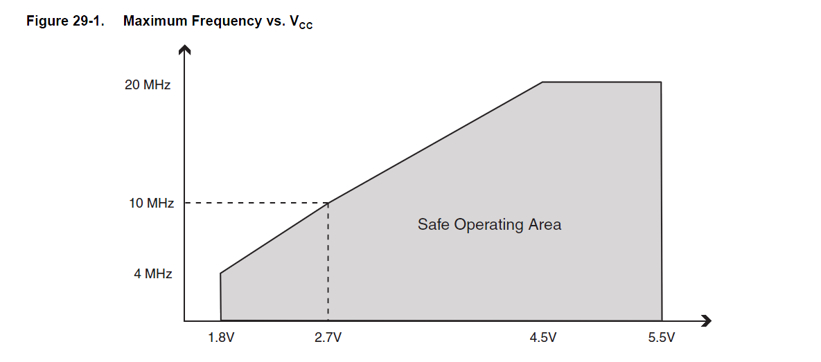
The ATmega328P microcontroller in a deep sleep consumes tiny amount of energy ~4uA, but to operate at the lowest voltage (1.8V) 4MHz oscillator should be used.
 The next thing to check is the voltage range of the used components:
- Supercapacitor: 0 - 5.5V
- MCU: 1.8 - 5.5V
- Sensor1: 2.1 - 3.6V
- Sensor2: 1.5 - 3.6V
- Sensor3: 1.5 - 5V
- RF transmitter: 1.8 - 3.6V
- Solar panel 0 - 5.5V
The easiest way was to use a low-drop voltage regulator and get a stable supply voltage (3.3V) for all components. But after a bit of testing I found out, that when the voltage drops below ~3.3V LDO becomes inefficient and consumes an additional 20uA (or even more) that's drain supercap too quickly.
An alternative solution will be charging supercapacitor to 3.6V max and do not use any voltage regulators. It's much more efficient and in such a configuration I achieved 42 hours of work from a 1F supercap.
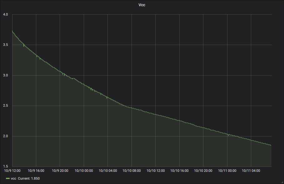
Saying this I should highlight, that the node sends data every minute when the voltage above 2.7V, and every 3 minutes in other case.
At this stage, two additional problems should be solved:
- Overvoltage protection
- Undervoltage protection
Overvoltage protection
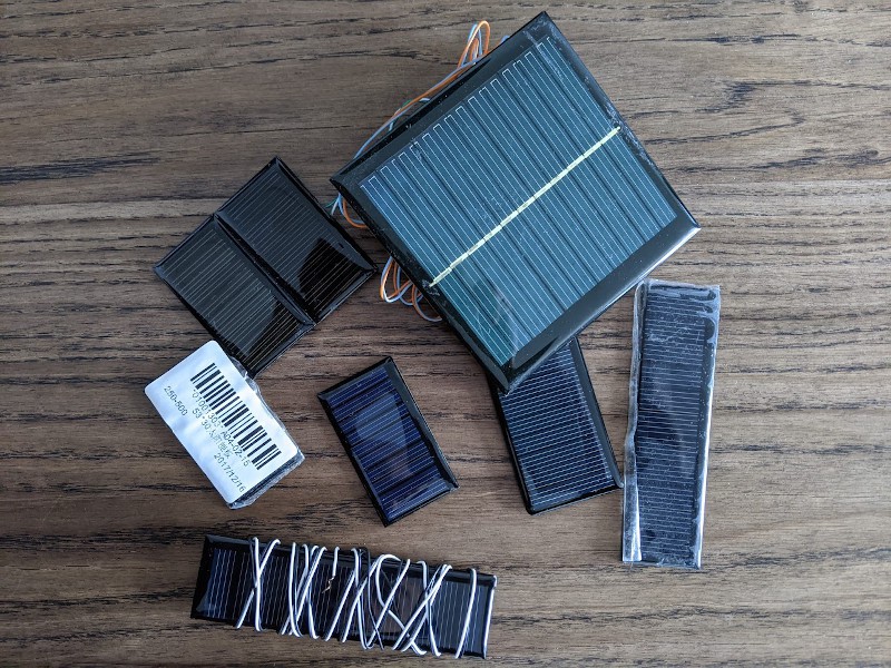
I have a bunch of different solar panels, the smallest one, which I plan to use in this project, at the direct sunlight produces 5.5V without the load and can produce more than required 3.6V with the load, so it should be limited somehow.
I always try to use the easiest solution, but usually, it doesn't work =D. In this case, the easiest option was to use a zener diode, but to work properly zener diode requires some amount of current through it (this can be around 5 to 10 mA), and if this requirement is violated it works non-linearly. For my project, 5mA (continuously) is a huge amount of energy. In most cases, the solar panel won't produce more than 0.5 - 1mA, as I don't expect to see the direct sunlight on the node (for obvious reason, it is a thermometer).
By now, I've already had a circuit for the undervoltage protection based on a voltage comparator, so decided to use a similar approach here. The image below shows the base schematic and LTspice simulation results.
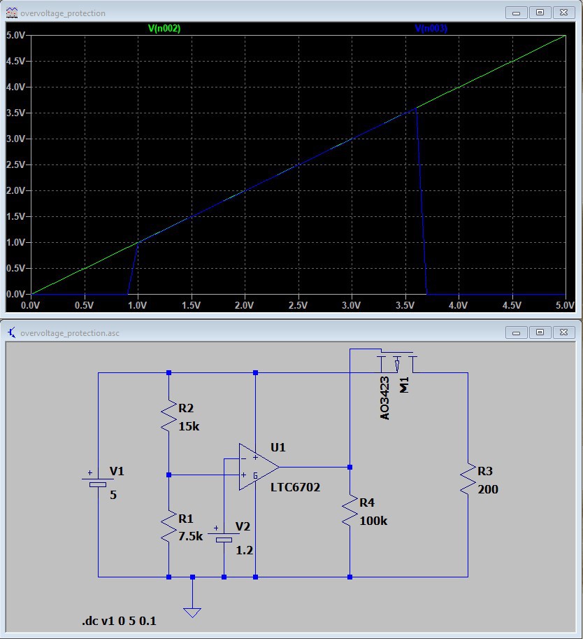
The circuit isn't perfect. When the supercapacitor is discharged and the solar panel produces 5V, it'll continuously switch on/off charging at the point near 0.9V. I'm not sure that this is a significant disadvantage, it almost like MPPT (except that it won't be the max point). I'll test it in real-life to see how it works or does it work at all.
Undervoltage protection
At some stage of the supercapacitor discharge, we will face the situation when the voltage is too low (<1.8V) and the node should be shut down. ATmega328P includes built-in brown-out detection (BOD) that keeps MCU in the reset state when the voltage is less than some threshold, but it has a price.
Let's imagine a situation: a supercapacitor is fully discharged, a solar panel produces 5V 1mA. Everything is okay at first glance, the solar panel should slowly charge the supercap, and when it reaches 1.8V BOD turns the MCU on. Spoiler alert: it won't work! In the reset state, the MCU consumes an unstated amount of current (3-5mA according to my experiments) and it'll eat all available energy preventing the supercapacitor from charging. That's why external low-power undervoltage protection is required.
With the big help of r/AskElectronics subreddit and u/bigger-hammer in particular) this circuit has been created
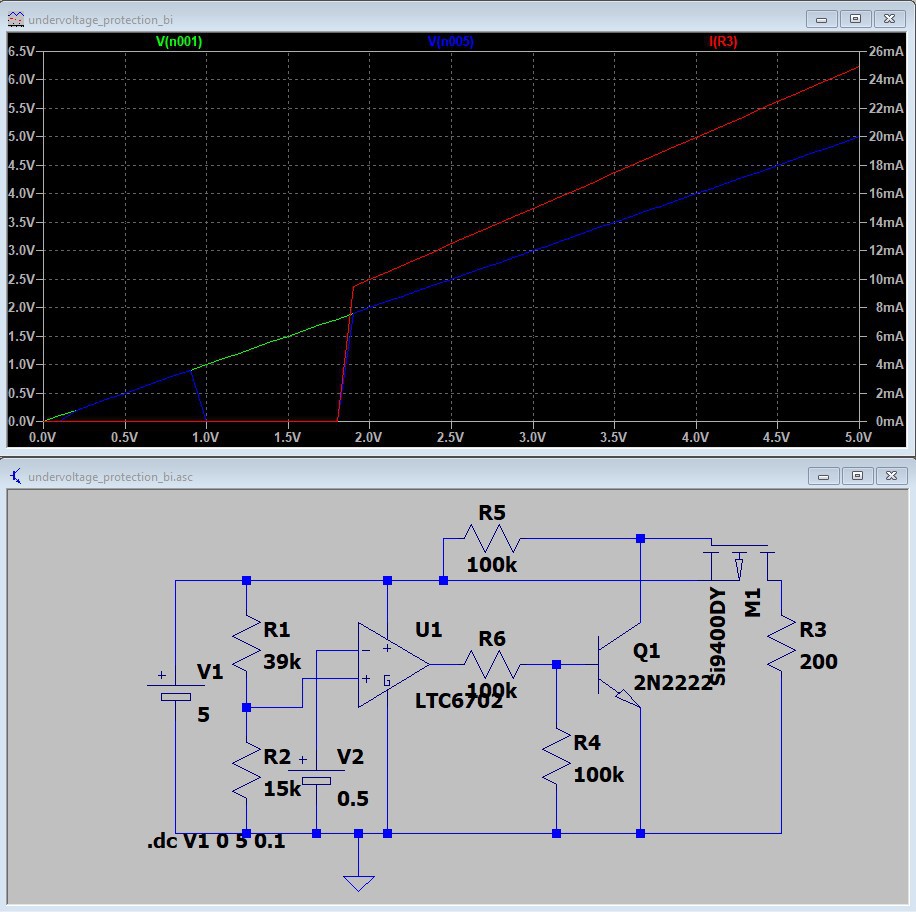
The green line is a supply voltage, read one is a voltage on the load.
In both circuits, I'm going to use a different voltage comparator with better parameters and lower power consumption, but it isn't available in LTspice.
What next?
I've ordered PCBs and required components, but they haven't arrived yet. All those things should work in theory, but will they? A separate question is: what will be the final power consumption with all those additional components? Will see :)
PS
If you see grammatical or structural mistakes, please PM me.
Discussions
Become a Hackaday.io Member
Create an account to leave a comment. Already have an account? Log In.
So i have achieved the desired results for the transmission part , ~1400 transmissions with a 1.5F 5.5v cap,8sec frequency,1.8V,1mhz, bod disabled.As @strange.rand suggested , the issue was down to two things.The fresh cap had to be conditioned,ie charged fully to 5V and left for some time before discharging . Also Lora at full power 17db required ~80 ma which also attributed to low numbers, i have made it half power which gave me approx 3km range still.So all good so far, thanks!
Are you sure? yes | no
Cool! You should also take into account voltage drop during the transmission, otherwise, you'll lose power at the late stages of discharge.
I've just finished initial testing of the 4700uF low ESR capacitor, it stopped leaking current after some time and I even got a longer discharge time 23.5h with the additional capacitor, 21.5h without (from 3.3V to 2.4V).
Are you sure? yes | no
I will check that out too..im using 1000uf so far..interesting thing to note here is both lora and atmega operated down till 1.6v ! Rssi came down though after dipping down from 1.8v. Voltage drop during transmission was very minimal,didnt check exact measurement since i also dont have good tools.
Are you sure? yes | no
You can reduce your component count significantly, and simplify the circuit, by just using a simple voltage monitor IC. They come available in a bunch of different trip point voltages, and typically only consume 1uA or less. You might need only the IC and a mosfet.
Hit digikey and go to PMIC - Supervisors
https://www.digikey.com/en/products/filter/pmic-supervisors/691
One example (I think digikey is obsoleting it though, but just a reference point) good to 6V, trip point at 1.7V,
https://www.ablic.com/en/doc/datasheet/voltage_detector/S809xxC_E.pdf
Are you sure? yes | no
Thank you for your comment, Martin.
Before playing with voltage comparators, I tried to find some "single-chip" solution but didn't found a suitable one (probably, I used improper keywords for googling).
The example you showed is really promising! I'll further research PMIC - Supervisors.
As an alternative for the charging circuit, I can use a precision shunt regulator (e.g. TS432) it has an acceptable output current. I've already ordered one and will try to use it.
Are you sure? yes | no
https://www.onsemi.com/pub/Collateral/NCP300-D.PDF 0.5uA standby current as a more valid current example (at $0.53 ea qty 1 with availability at digikey, with voltage set points at 1.8, 2.0, etc). I was mostly looking at them for the quiescent power consumption to keep the power budget at a minimum. The TS432 shows a 60uA quiescent current...
Good luck and happy hunting!
Are you sure? yes | no
Yes, for undervoltage protection the current consumption is highly important (I even found one with 350 nA typical), but for the charging part, which operates from the solar panel directly, 60uA is more o less okay.
In the case of TS432, I would use a direct connection without a MOSFET. But it's good to have options. Probably, I'll try both ways before selecting the final one.
Thank you.
Are you sure? yes | no
I figured out why it is less for me...somehow my capacitor's self discharge is way high, around 0.01v per second discharge without anything connected to it!Tried with several different caps(10F,2.7v) still the discharge is high.Any idea why?
Are you sure? yes | no
I think it happens only at the beginning, no? I have a few 1.5F supercapacitors, so I'll try to measure self-discharge rate.
Are you sure? yes | no
For a 10F 2.7v, charged upto 2.5v,it self discharges to 1.7v in less than 30mins after which it becomes constant.Is this supposed to be like that?How much is your Esr rating,glad if you could post the make of the one you are using.Im using elna dynacap,esr not sure.
Are you sure? yes | no
I have different supercaps https://i.imgur.com/QhgkRtH.jpg
That black 1.5F should be SE-5R5155ZCHV https://radiolux.com.ua/files/pdf/1_5F.pdf It costs less than $1 locally.
Are you sure that they a fully charged? My charging process:
1. Lab power supply configured to constant current 10mA, 3.6V.
2. After connecting supercap, voltage drops to almost 0V and then slowly raise.
3. When it reaches 3.6V, it still consumes 10mA for a minute or so.
4. When the power supply shows 0mA consumption I keep it connected for one additional minute.
UPD
Try to charge supercap to 5V, discharge to ~2V, charge to 3.6V and then test.
Are you sure? yes | no
Hi, i had a question on the setup which made it possible for you to run 42 hours with 1 minute send frequency just using the supercap. What was your current consumption during transmission and for how long was each transmission? How many number of transmissions were made.
Are you sure? yes | no
Something should be completely wrong with your circuit/code if you are able to get only 8 transmissions with 1.5F supercap.
1. Measure your power consumption during deep sleep, it should be < 10uA, if no - you have a problem. In my case, it is 4uA with one sensor.
2. Do you use a Schottky diode to protect from reverse current leakage? (from the supercap to a charging circuit)
3. BOD should be disabled, at least before entering deep sleep (it consumes 20uA).
I don't have a good instrument to measure current during the transmission, because it is quite a fast process (a bit more info in a next log), but let's calculate the worst-case scenario: 8s sleep - 10uA, 15ms transmission - 45mA, 45ms idle - 3mA, average power consumption - 110uA (it is a lot). Then use this to calculate the discharge curve: http://www.circuits.dk/calculator_capacitor_discharge.htm
It will give you more than 9 hours from 3.6V to 1.8V.
Are you sure? yes | no
I was in the process of editing my original question with my new findings while you were replying :).I am getting now a total of around 600 transmissions (freq per 8sec).I am following exactly as you mentioned for points 1,2,3 above.Bit strange that I think I am leaking more current during transmission,sleep current is 6uA.Will debug and find out more.Thanks!
Are you sure? yes | no
jatayu86, ~900 transmissions in my case (1F supercap)
Are you sure? yes | no