0%
0%
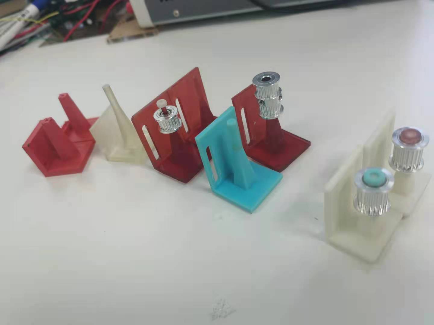
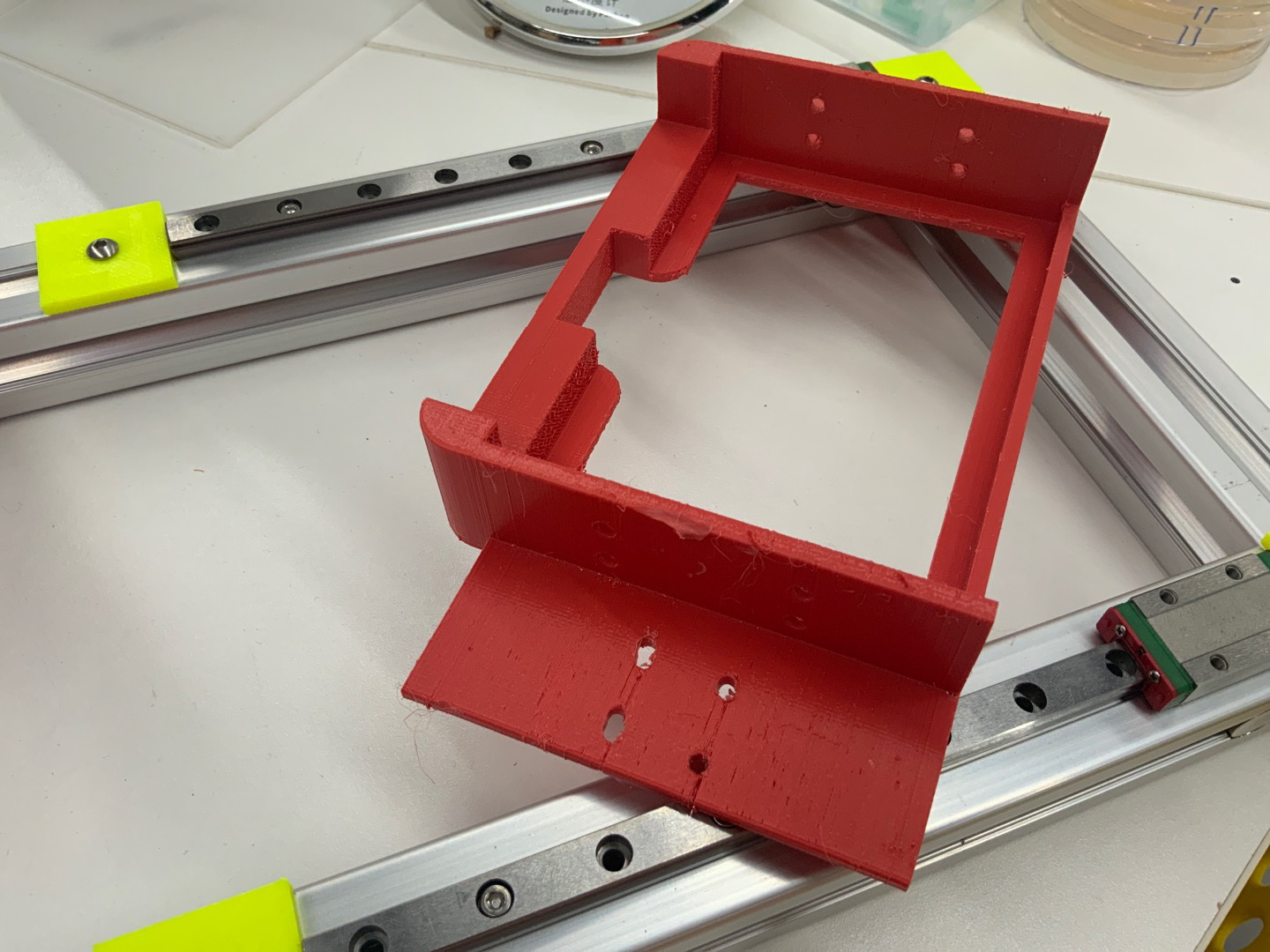
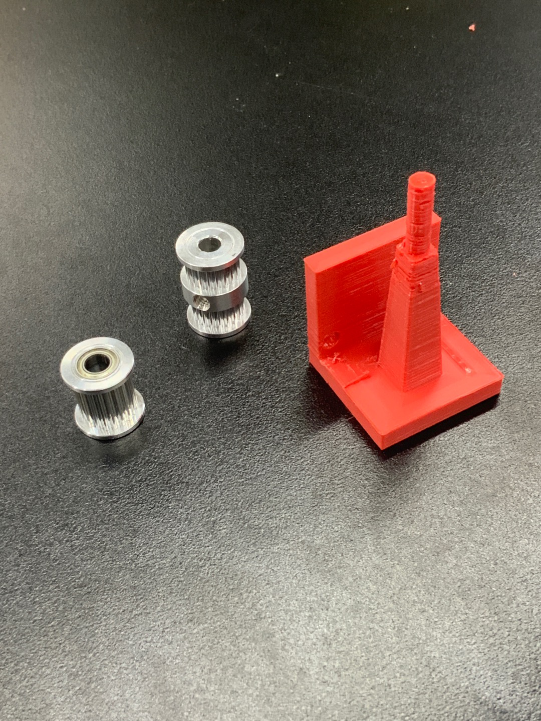
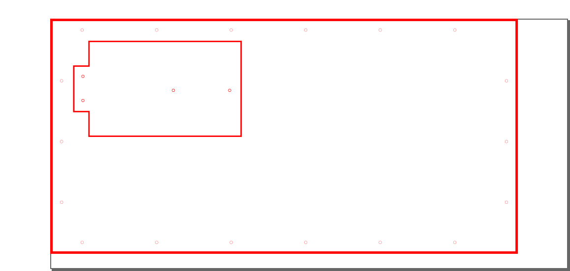
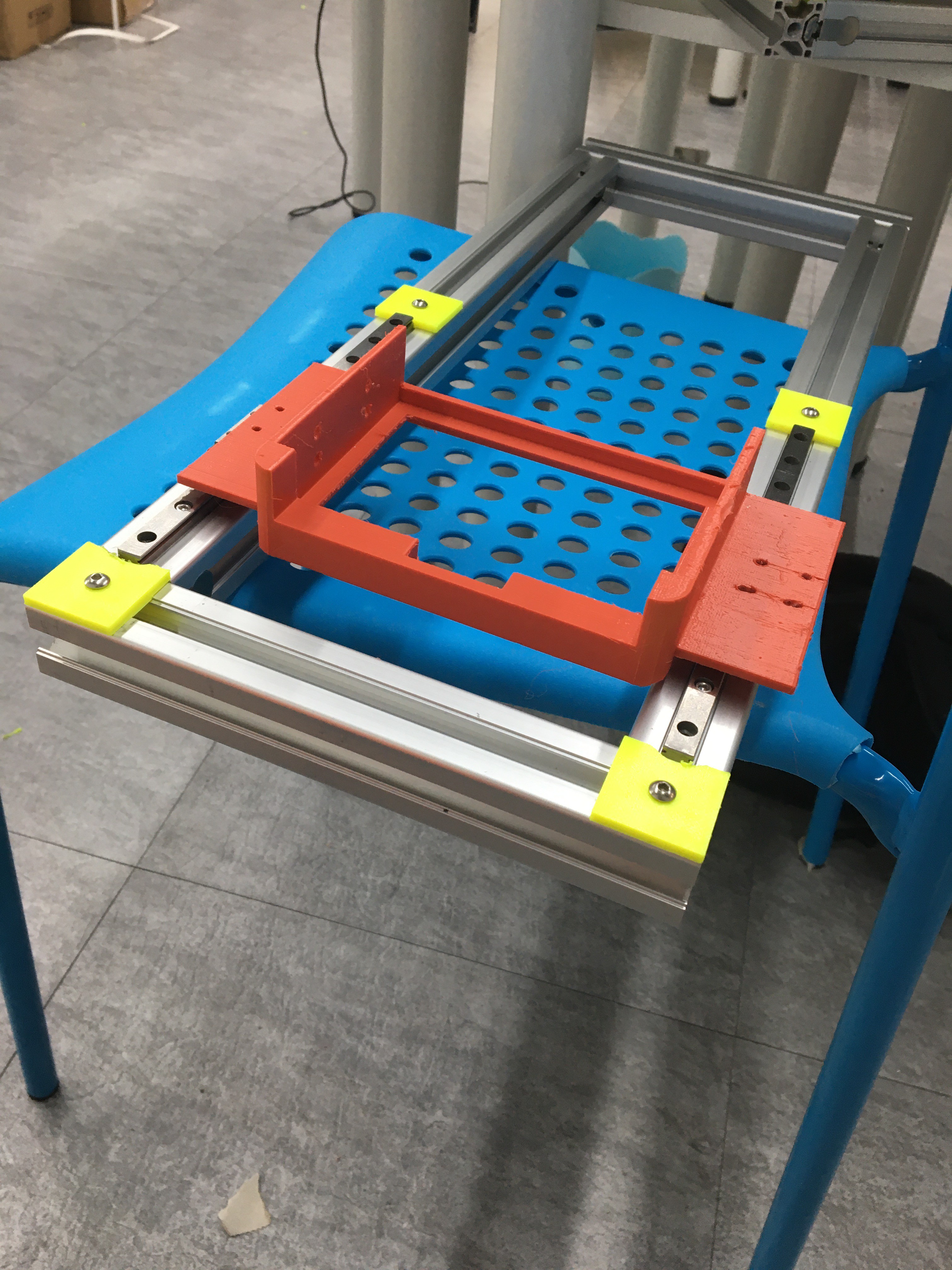
Our Microplate Reader
not just a test now :D
progress records of a group of high school students building a microplate reader
yeah
 aha!
aha!Become a Hackaday.io member
Already have an account? Log in.
Just one more thing
To make the experience fit your profile, pick a username and tell us what interests you.
Pick an awesome username
hackaday.io/
Your profile's URL: hackaday.io/username. Max 25 alphanumeric characters.
Pick a few interests
Projects that share your interests
People that share your interests
 Roni Bandini
 Guillermo Perez Guillen
 Arnov Sharma
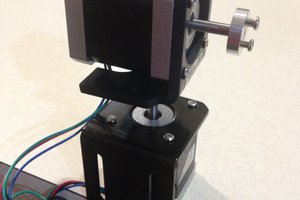
 agp.cooper