 Bud Bennett
Normally, I would use a simulator to verify the correctness of the design, but Microchip's simulator for the PIC16F18313, that runs under its MPLABX IDE, doesn't implement the Master Synchronous Serial Port peripheral. I have a PicKit4 programmer/debugger (not a clone). I thought that it would be easier to work with DIP parts than SOICs using a ZIF socket, so I purchased 4 PIC16F18313 DIPs from Digikey.
The PicKit4 blew up the first 3 parts that I tried to program. All the program was supposed to do was toggle an output pin at a 1 second rate after configuring all of the peripherals. This was a problem that I was familiar with -- my previous work-around was to use low voltage programming. But all of the pins on this chip were being used as I/O and LVP was not allowed if the MCLRE config bit was not set.
I finally trolled the internet to see if others were having this problem and found this YouTube video. The guy that posted the video said that Microchip had posted a technical note for a fix to the PicKit4 on it website -- ETN #37 MPLAB® PICkit 4 VPP Overshoot Modification. I was going to implement the suggested mod, but something was fishy between the provided schematic and the photo of the mod on the PCB:
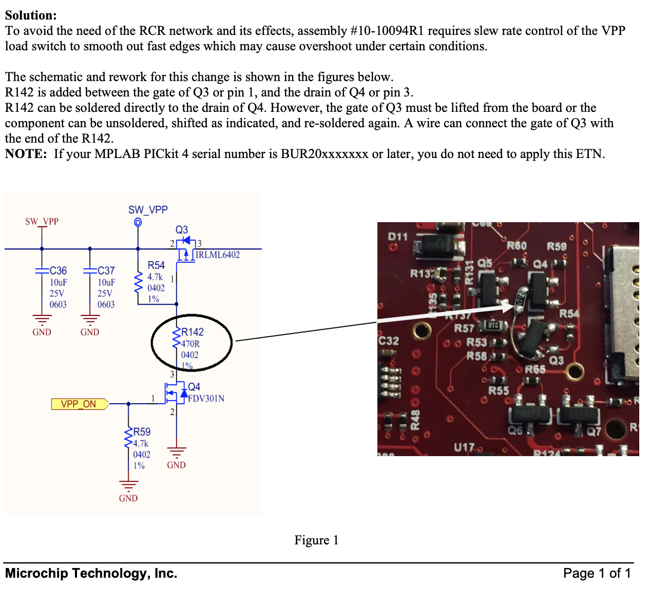
The schematic seems OK to me, but the image shows that they disconnected the gate of Q3 from R54 and connected R142. This doesn't match the schematic. It seemed to me that they could not have properly tested the fix if the implementation was incorrect. I contacted Microchip, told them about the ETN issue and the YouTube video, and asked them to send a replacement for my PicKit4 (serial #BUR18XXXXX). In the meantime I implemented the 120Ω resistor at the VPP pin of my old PicKit4, which was recommended by the guy in the YouTube video. While this purported fix allowed me to program the PIC with the correct function, the current drain after programming increased from an expected 20µA to between 16mA and 60mA. Something still wasn't right and now all of my PIC16F18313 DIPs were gone. I had a PIC16F18323, which is just a 313 with 14 pins. When the new PicKit4 arrived I was able to program the 14pin DIP without damaging it. It's the only DIP part that I have left.
Microchip requested that I send the defective PicKit4 back to them at my expense...FAT CHANCE!
The Breadboard:
The LIS3DH accelerometer is mounted on an Adafruit breakout board. The passives are just bypass caps and a current limit resistor for the LED, which substitutes for the buzzer.

I hot glued a 15400 battery holder for the li-Ion power source allow the entire unit to be tossed for testing. At this point I have enough code working to configure the LIS3DH to detect a free-fall event lasting 400ms and assert an interrupt to the PIC. The PIC then activates the buzzer in this pattern: 20 50ms bursts lasting 2 seconds, then a 100ms burst every 2 seconds over the remaining 10 seconds. Then the PIC goes back to sleep until interrupted by the accelerometer and the cycle repeats. The buzzer pattern may change after observing Lucy's pursuit timeline with her chiming ball.
Next step is to add a battery monitor to announce when the battery requires recharge.
Discussions
Become a Hackaday.io Member
Create an account to leave a comment. Already have an account? Log In.