Close
0%
0%

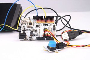
Cassette interface for FPGAs

Now your FPGA-based retro computer can have its own mass storage too - just like it did circa 1980!

Public Chat
Similar projects worth following
I dedicate this little project to memory of Zoran Modli - maybe some aliens 35 light years away are picking up his cassette signals now...)

Main features:
- based on binary FSK (frequency shift keying)
- uses A/D converter on FPGA board
- no FFT or Goertzel to detect incoming frequencies
- speeds of 300 and 600bps are reliable, 1200 needs some "fine screwdriver tuning"
- interface is simple UART
- what goes out on TXD is recorded, what comes back from played tape is transmitted on RXD
- any other "audio-friendly" media can be used instead of the tape - from recording as wave files to broadcasting on air ( https://en.wikipedia.org/wiki/Ventilator_202#Broadcasting_Computer_Software )

Refer to "record" and "play" log entries for the descriptions of the design and implementation.

sys_cas_mercury.bit

Binary to be uploaded to Mercury + Baseboard Switches to be set (7 downto 0): 00111100 (600bps, 8bits, no parity, 2 stop bits, show bps on 7seg LEDs)

bit - 146.11 kB - 11/11/2020 at 07:15

Download

View all 8 components

  • Play

    zpekic11/02/2020 at 06:51 0 comments

    Instruction to retrieve data from the tape:

    1. select baudrate and serial mode on Mercury baseboard switches 7 - 2, for example 000110XX will set 300bps, 8 bits, odd parity, 1 stop bits (Note: 1200 bps will work with high quality recorder/tape and finely tuned volume and tone. 600 and 300 is much less demanding)
    2. use same setting on your Terminal software on the PC (for example TeraTerm)
    3. establish all wire connections (AUDIO_OUT > MIC, AUDIO IN < SPKR, PMOD USB to PC USB)
    4. rewind the tape to required position (as marked in your catalog)
    5. press PLAY
    6. watch data from the tape on the terminal console - if these were valid ASCII, it will be text, otherwise bytes beyond ASCII range will be printed according to current character set mapping (and the BELL character 0x07 will sound too!) HEX file or similar format can encode binary while still be human readable and are good candidates to use as format due to wide support and basic checksum integrity checking.
    7. press STOP when UART blinking stops (otherwise junk beyond last good written position can be picked up)

    Principle of operation:

    (refer to https://github.com/zpekic/Sys_cas/blob/main/Mercury/tapeuart.vhd )

    Remember, recording was done using simple "binary frequency shift keying" with following parameters:

    bpsmark ("1") frequency (Hz)space ("0") frequency (Hz)fmark
    ----
    bps
    fspace
    ----
    bps
    3004800120084
    6009600480084
    120019200960084

    Result is a distorted waveform on the tape, but which still holds the primary mark and space frequencies. The task is to figure out those frequencies in real time, and based on which one is detected, output 0 or 1 which will be the UART output (TXD).

    This is of course a classic FFT or Goertzel algorithm problem, but neither of those is used here. The brute force of FPGA and high bandwidth of modern A/D adapters is used instead, with some simple hacky tricks. Here are the steps:

    1. Connect the available A/D converter and drive it to sample tape data

    The Mercury baseboard uses the A/D converter described here. I used the driver code provided as a sample. The clock is 25MHz, and the sampling frequency 0.75MHz - both are clearly overkill for the purpose, but they are easily obtainable by simple clock dividers. The channel is either of the audio left or right.

      -- Mercury ADC component
      ADC : entity work.MercuryADC
        port map(
          clock    => adc_clk,
          trigger  => adc_trigger,
          diffn    => '0',
          channel  => "000",    -- channel 0 = left audio
          Dout     => adc_dout,
          OutVal   => adc_done,
          adc_miso => ADC_MISO,
          adc_mosi => ADC_MOSI,
          adc_cs   => ADC_CSN,
          adc_clk  => ADC_SCK
          );

    2. Process each A/D conversion 

    adc_done signal will pulse when the conversion is ready, at which point the data reading (strength of the signal from tape in 10-bit resolution should be analyzed) is presented at Dout port. We don't really care about the value, but the point where the value is very close to zero, hoping that moment indicates the period of the waveform that captures the main recorded mark/space frequency.

    Picking this threshold value can be tricky and depends on the characteristics of the signal path between audio input and A/D converter. In this case hex value 0x12 is selected, but to make it easier to figure it out, the min and max value (wave amplitude) is captured and can be displayed through debug port.

    When it is detected that previous value was close to zero but is now greater then 0x12 then 1 output is generated, otherwise 0. Note that there is a certain level of hysteresis in this as the previous value of f_in_audio is taken into account. 

    -- ADC sampling process
    on_adc_done : process (adc_done, f_in_audio)
    begin
     if (rising_edge(adc_done)) then
            if (f_in_audio = '0') then
                if (unsigned(adc_dout) > "00" & X"12") then -- 24
                    f_in_audio <= '1';
                end if;
            else
                if (unsigned(adc_dout) < "00" & X"12") then -- 24
                    f_in_audio <= '0';
                end if;
            end if;
                
            if (unsigned(adc_dout) > max) then
                max <= unsigned(adc_dout);
            end if;
    
            if (unsigned(adc_dout) < min) then...
    Read more »

  • Record

    zpekic11/02/2020 at 06:50 0 comments

    Instruction to record data onto the tape:

    1. select baudrate and serial mode on Mercury baseboard switches 7 - 2, for example 001111XX will set 600bps, 8 bits, no parity, 2 stop bits (Note: 1200 bps will work with high quality recorder/tape and finely tuned volume and tone. 600 and 300 is much less demanding)
    2. use same setting on your Terminal software on the PC (for example TeraTerm)
    3. establish all wire connections (AUDIO_OUT > MIC, AUDIO IN < SPKR, PMOD USB to PC USB)
    4. rewind the tape to required position (and mark to catalog position)
    5. press RECORD
    6. send file (or simply type) in terminal console window - all bytes outgoing will be recorded onto the tape. In order to later see the recorded data, the simplest way is to send text. For example any HEX file or similar format can encode binary while still be human readable.
    7. press STOP when UART blinking stops (and mark to catalog position)

    Principle of operation:

    (refer to https://github.com/zpekic/Sys_cas/blob/main/Mercury/tapeuart.vhd )

    The recording is simple "binary frequency shift keying" with following parameters:

    bpsmark ("1") frequency (Hz)space ("0") frequency (Hz)fmark
    ----
    bps
    fspace
    ----
    bps
    3004800120084
    6009600480084
    120019200960084

    All of this is accomplished with simple multiplexer that transfers one of two incoming frequencies above to audio_left and audio_right pins (no stereo signal, but mono replicated on both channels if tape recorder uses only one):

    -- output path
    f_out <= freq_space when (serin = '0') else freq_mark;    -- always output to audio
    audio_left  <= f_out; 
    audio_right <= f_out; 


    Given that frequencies are square waves which have infinite number of harmonics (sine waves), first of which is of the base frequency, and others rapidly attenuating odd multiples, and that these cannot be all stored on the tape, the signal that is actually stored is a distorted square/sine wave (see screenshot from oscilloscope). The D/A conversion happens on the path from FPGA output pin towards the tape. For other FPGA, a real D/A converter could be used which could easily generate very close approximation of a smooth sine wave of given mark/space frequency. But in the end it doesn't matter, as long as the receiver side can pick up the main harmonic component somehow from the analog signal recorded on the tape.

    It is important to note that regardless of baudrate, each "1" will always result in 8 cycles and each "0" of 4 cycles within the bit time. This big 2/1 difference allows differentiation between 1 and 0 on the receiving side, but presents a problem - mark frequency of 19.2KHz is close to the upper reliable frequency reproduction limit of a cassette tape.

View all 2 project logs

Enjoy this project?

Share

Discussions

Ken Yap wrote 11/02/2020 at 07:54 point

What's a "cassette"? 😉

Cool! 👍 Do you stll have a hexagonal pencil to rewind the tape?

  Are you sure? yes | no

zpekic wrote 11/02/2020 at 15:10 point

Yes I do! Good point I will add that to the list of components :-)

  Are you sure? yes | no

Ken Yap wrote 11/02/2020 at 23:27 point

🤣👍

  Are you sure? yes | no

Similar Projects

Does this project spark your interest?

Become a member to follow this project and never miss any updates