0%
0%
Bluetooth For 2008 Chrysler Grandvoyager
Bluetooth that actually works...
 Saabman
Become a Hackaday.io member
Already have an account? Log in.
Just one more thing
To make the experience fit your profile, pick a username and tell us what interests you.
Pick an awesome username
hackaday.io/
Your profile's URL: hackaday.io/username. Max 25 alphanumeric characters.
Pick a few interests
Projects that share your interests
People that share your interests


 Hulk
Hulk
 Capt. Flatus O'Flaherty ☠
 Rhys Morgan
 R. Scott Coppersmith
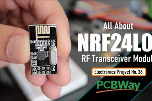
Cheers thanks for that - That is the module I am intending to use - I did look at some of the chinese units but they seem to give dubious results and the cost difference between the microchip product and the others is pretty negligable