0%
0%
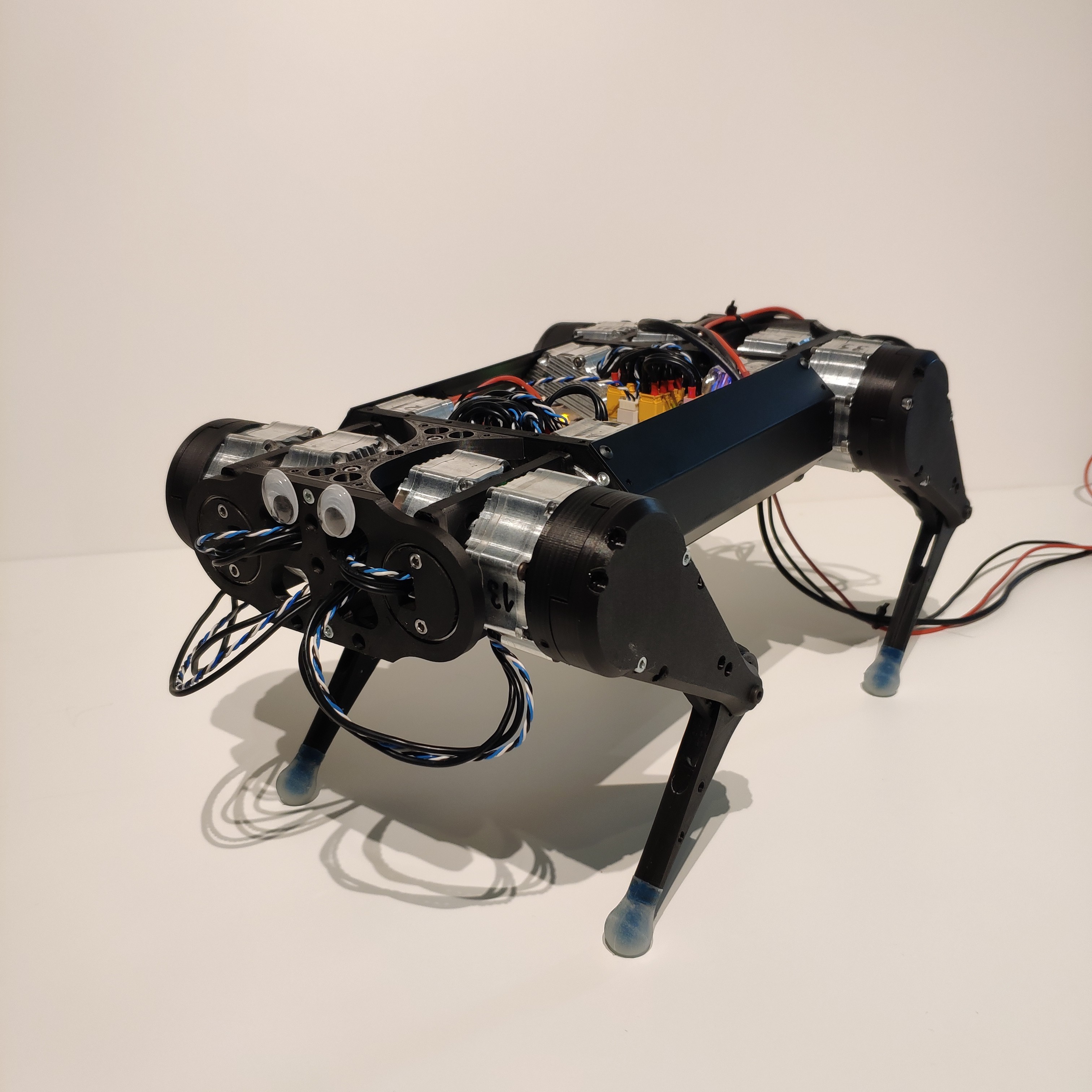
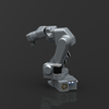
Wolfie
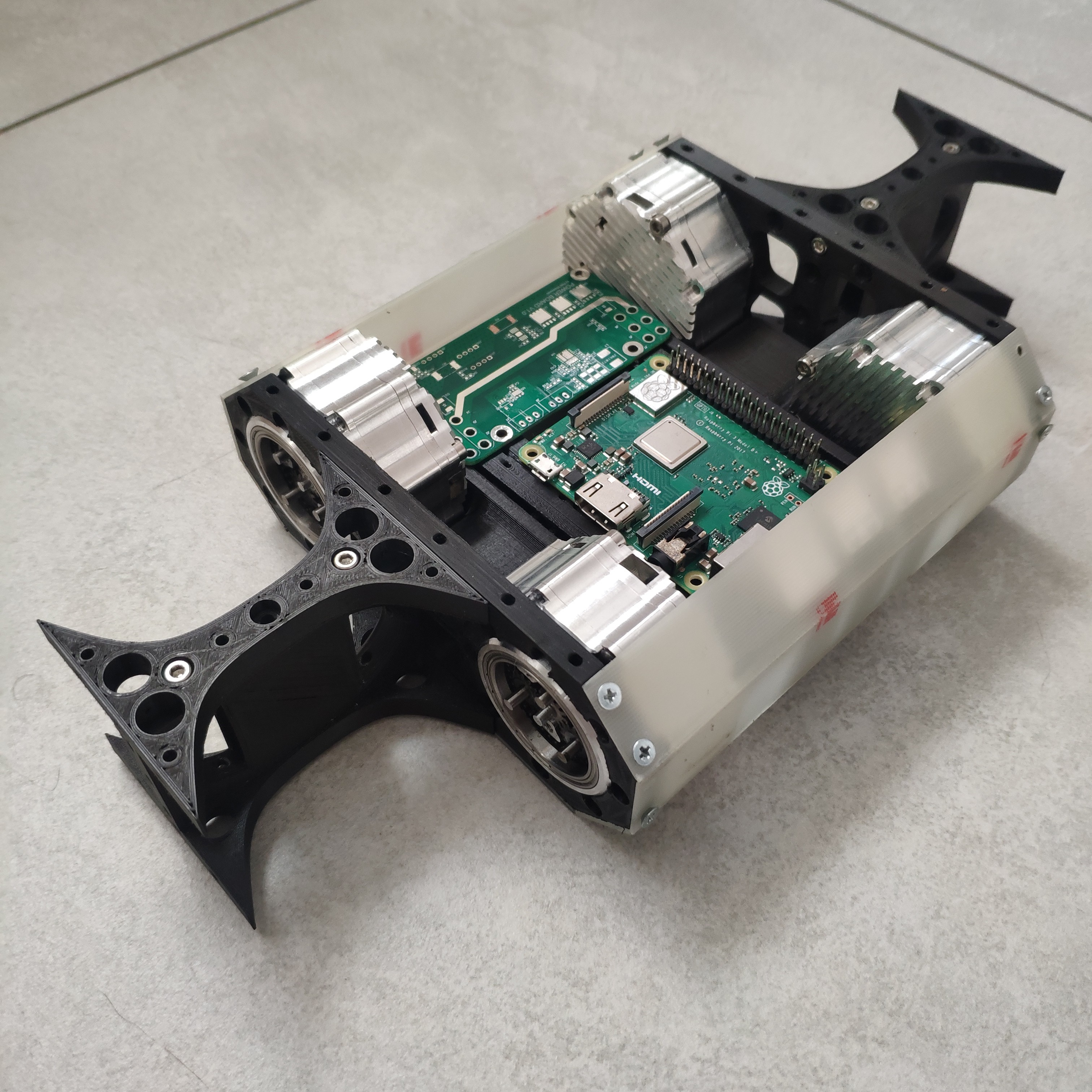
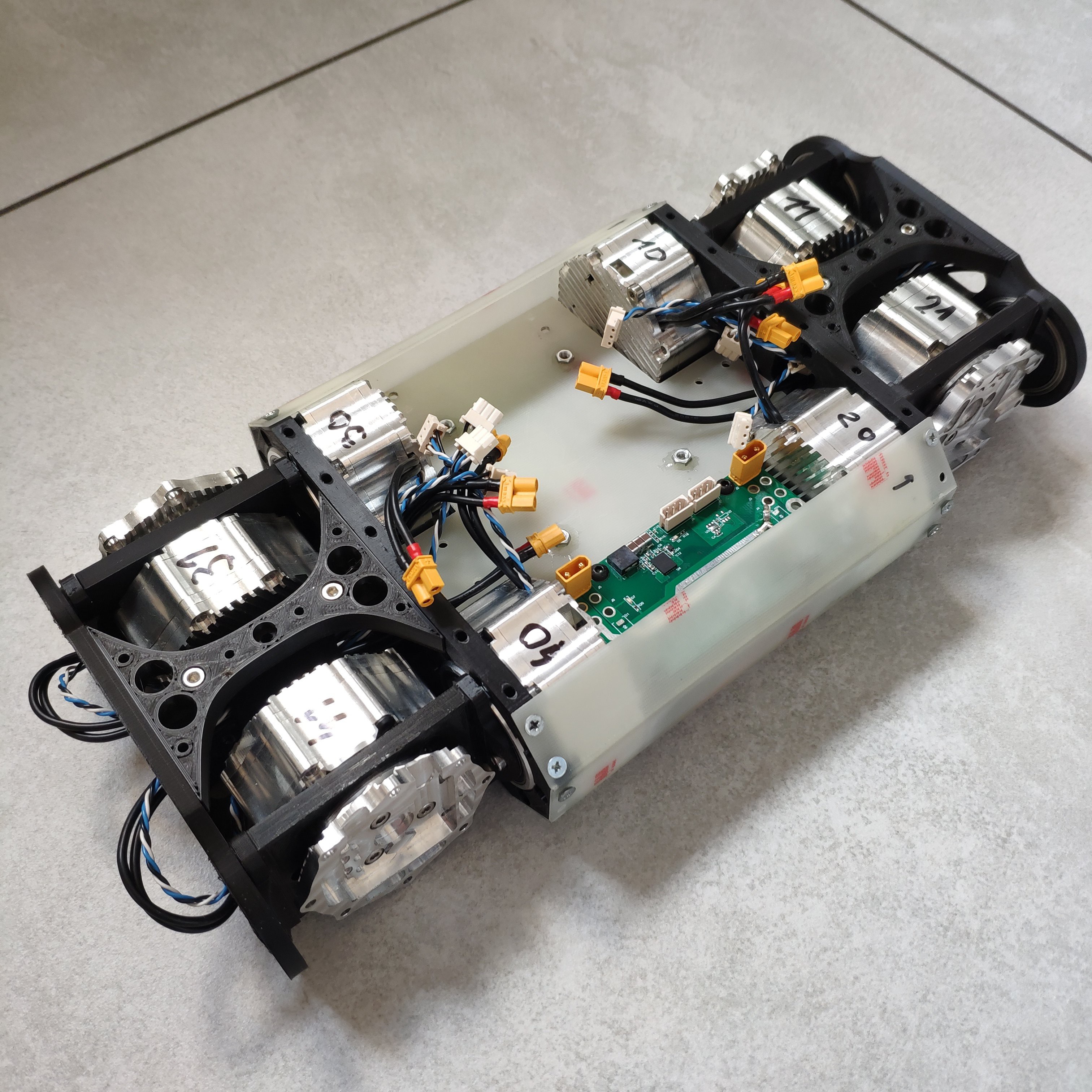
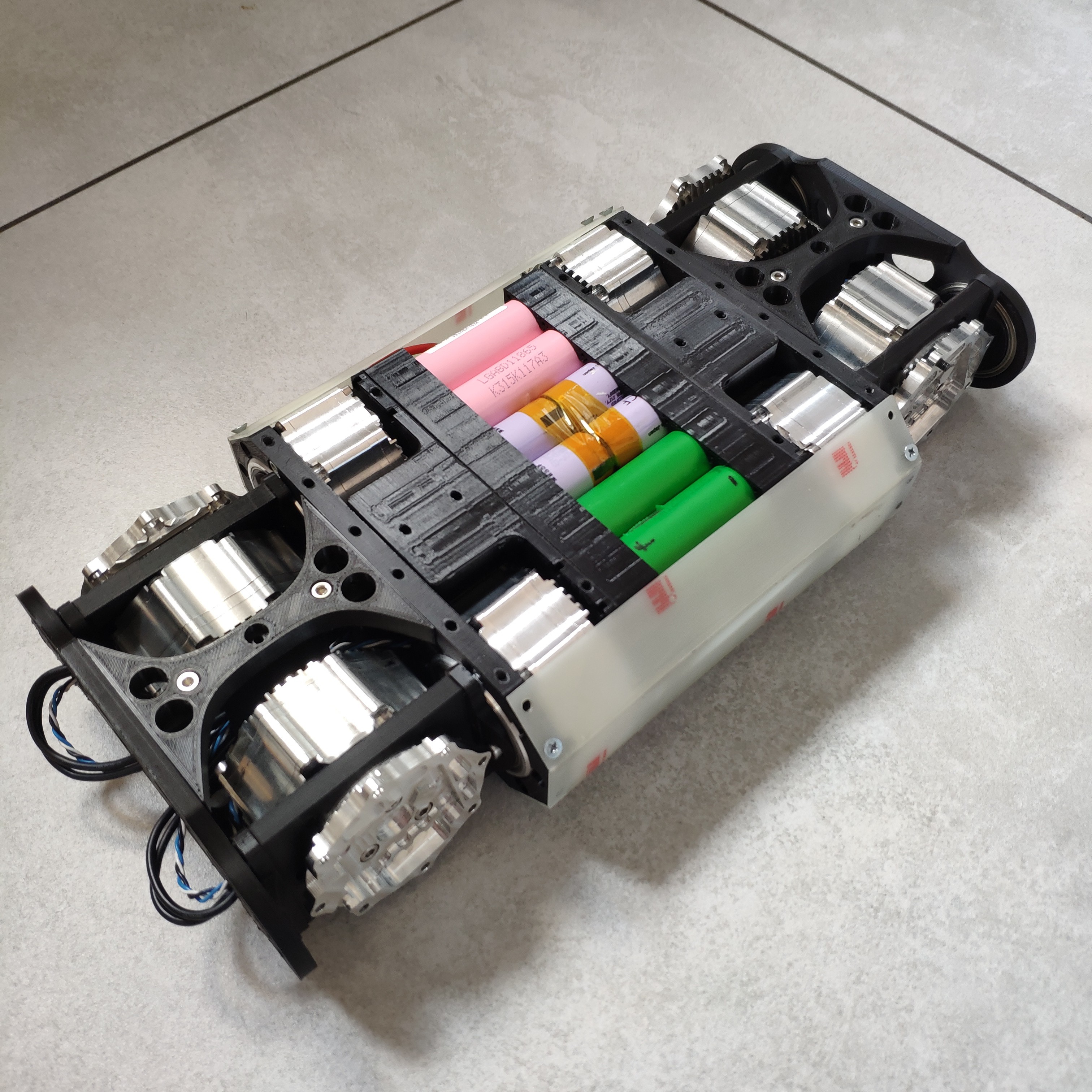
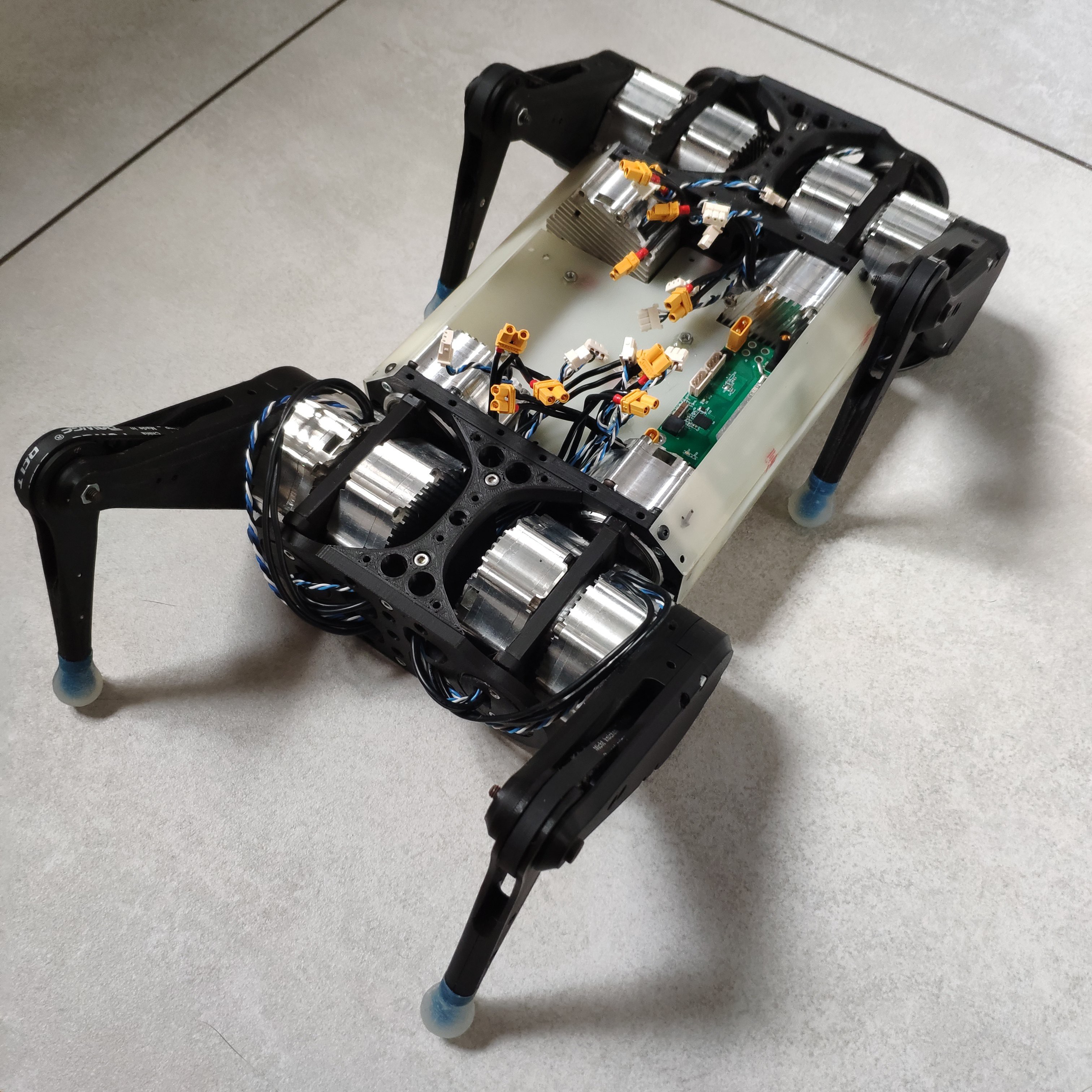
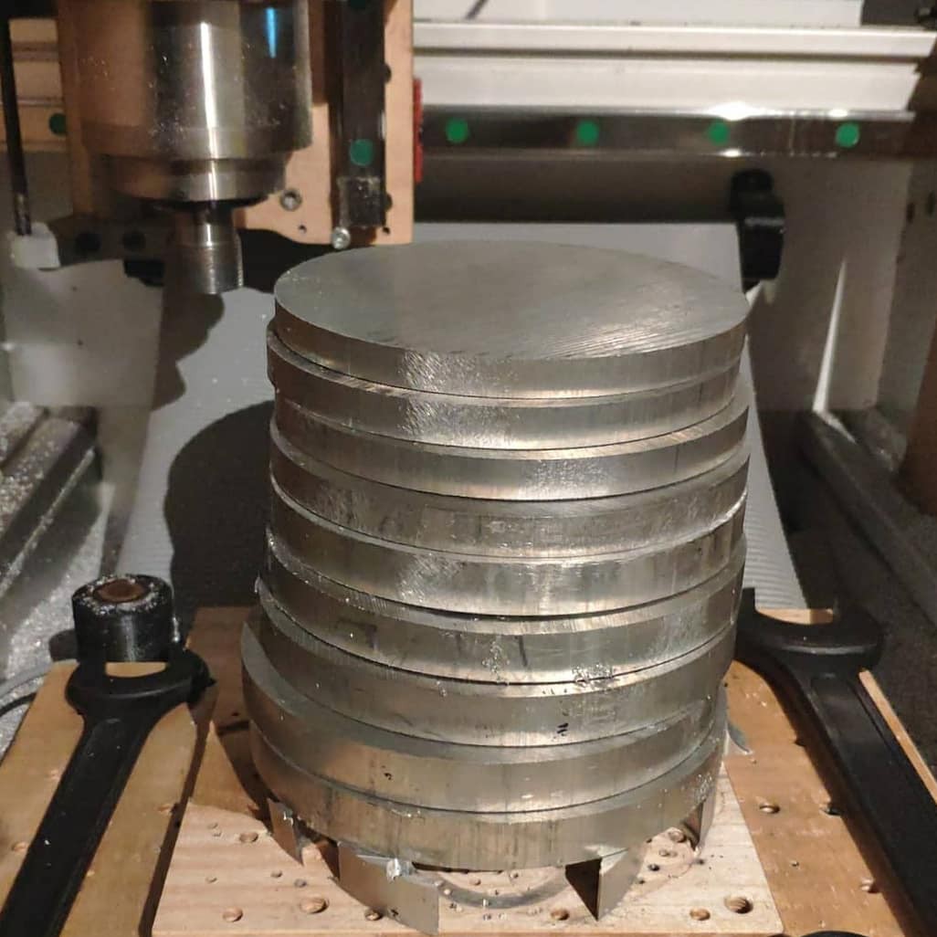
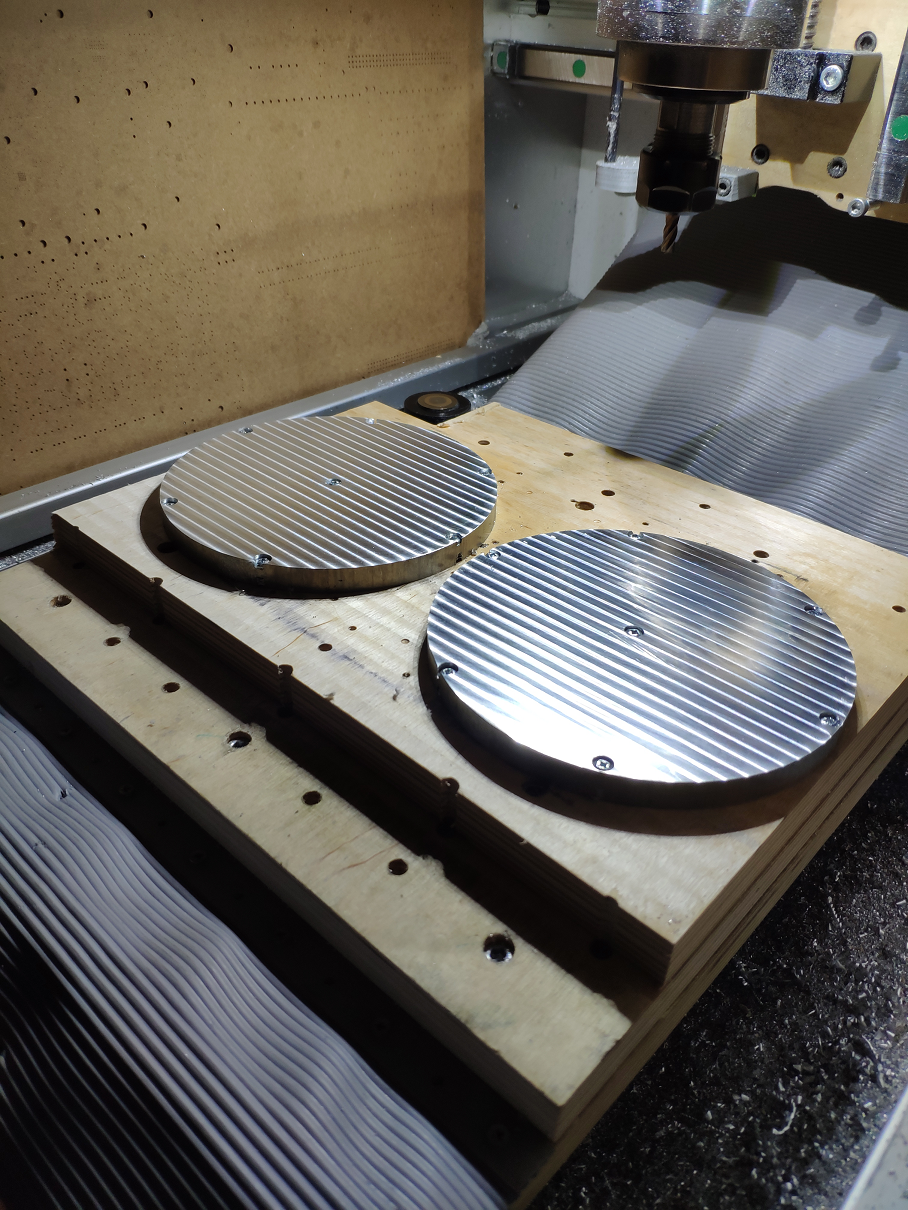
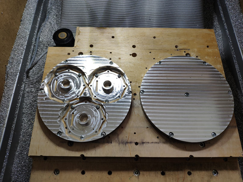
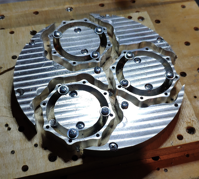
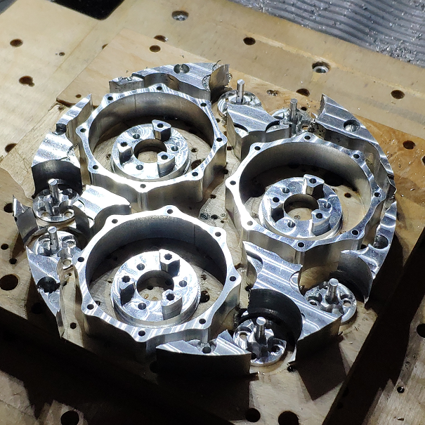
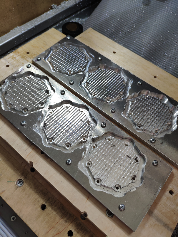
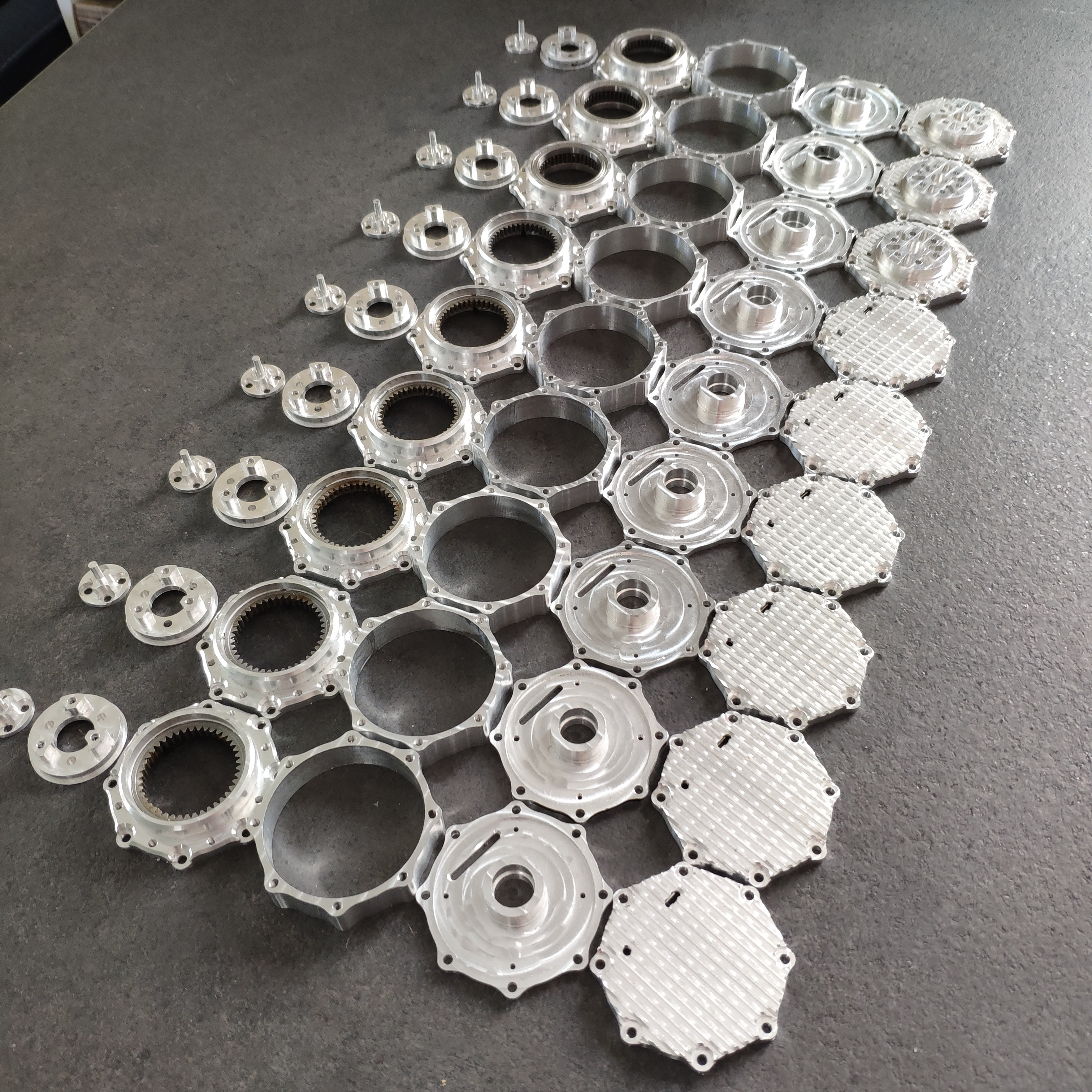
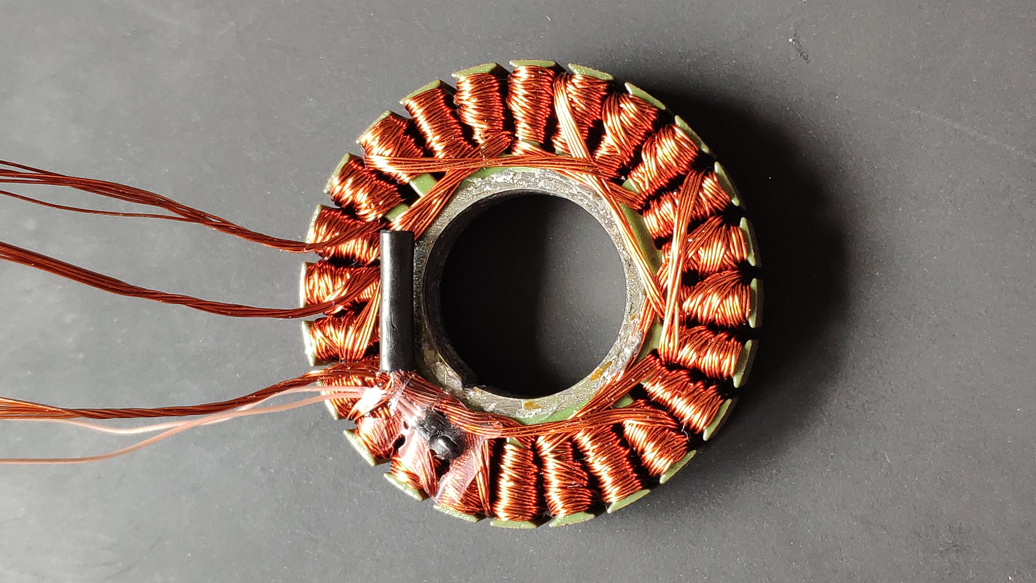
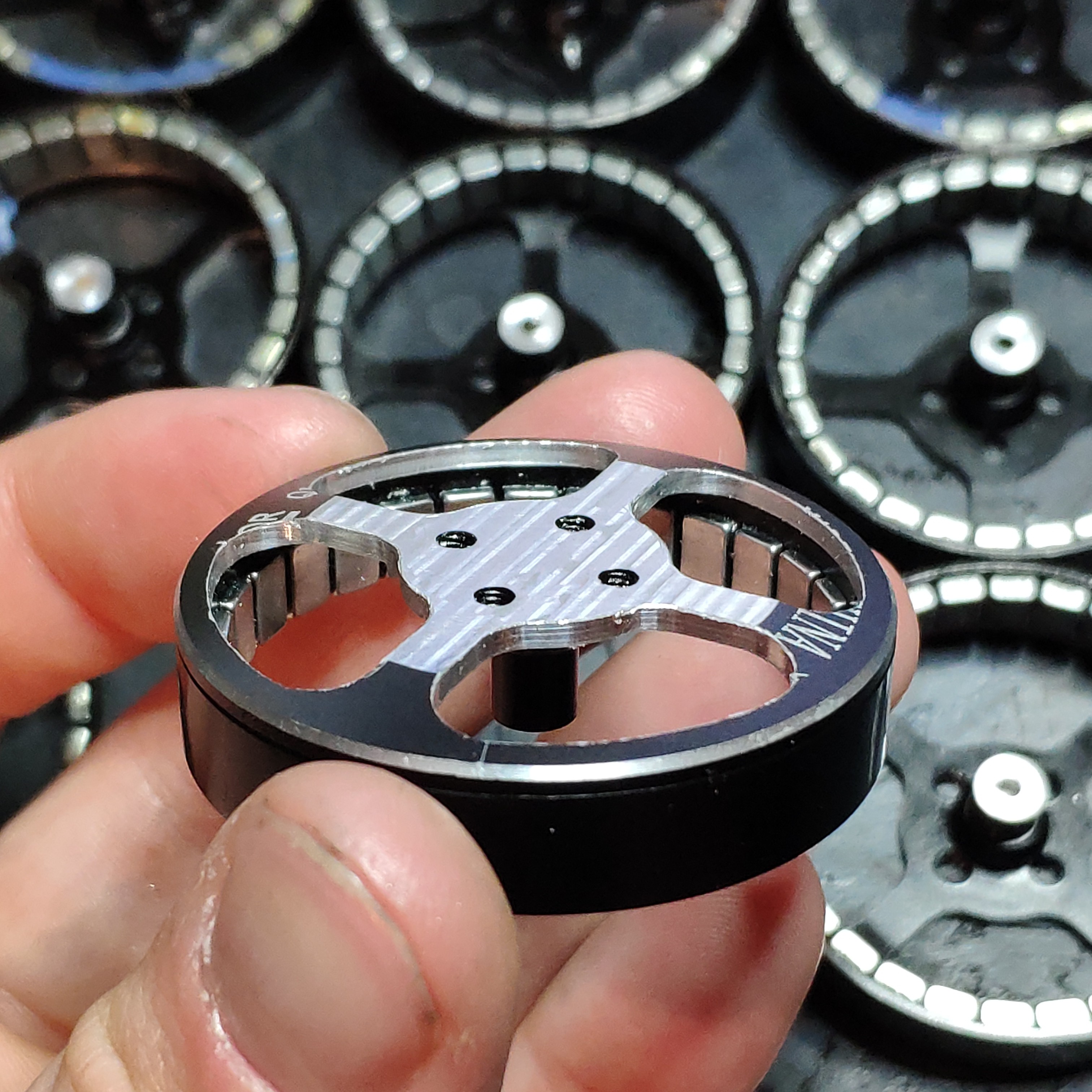
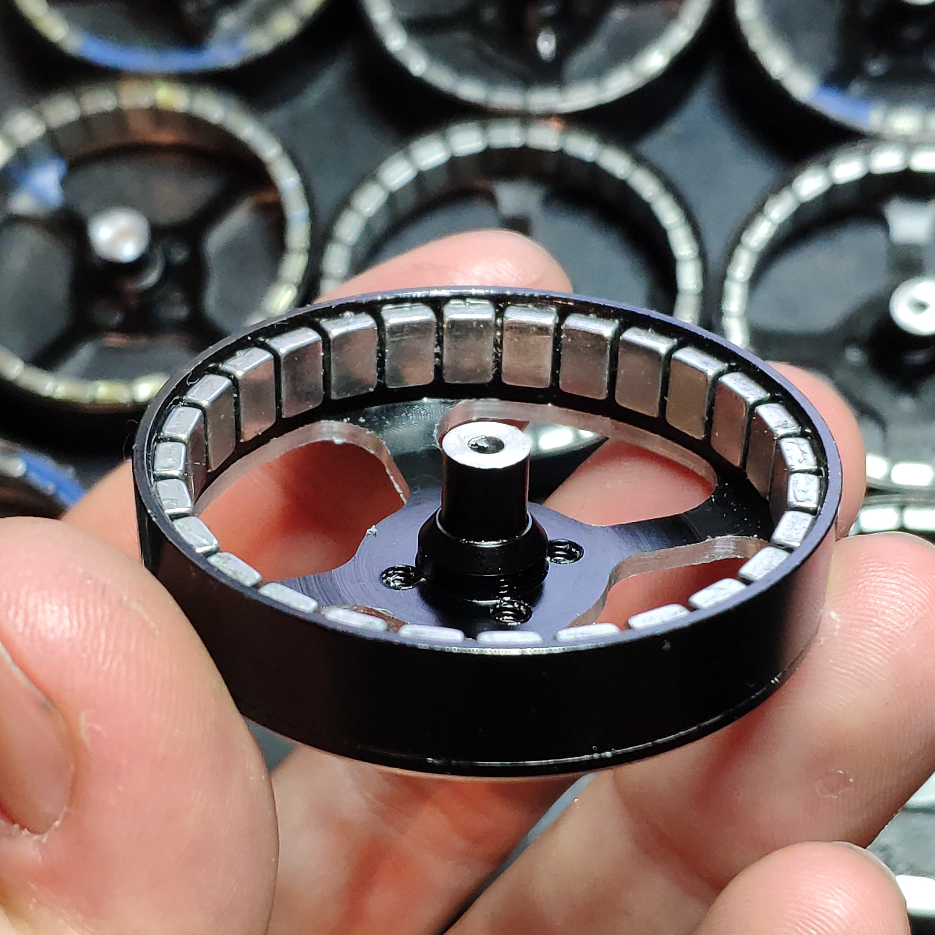
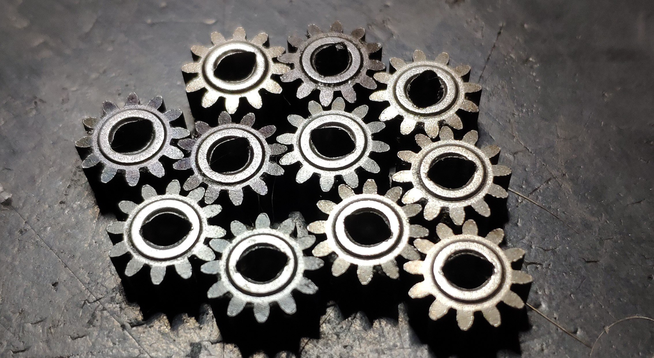
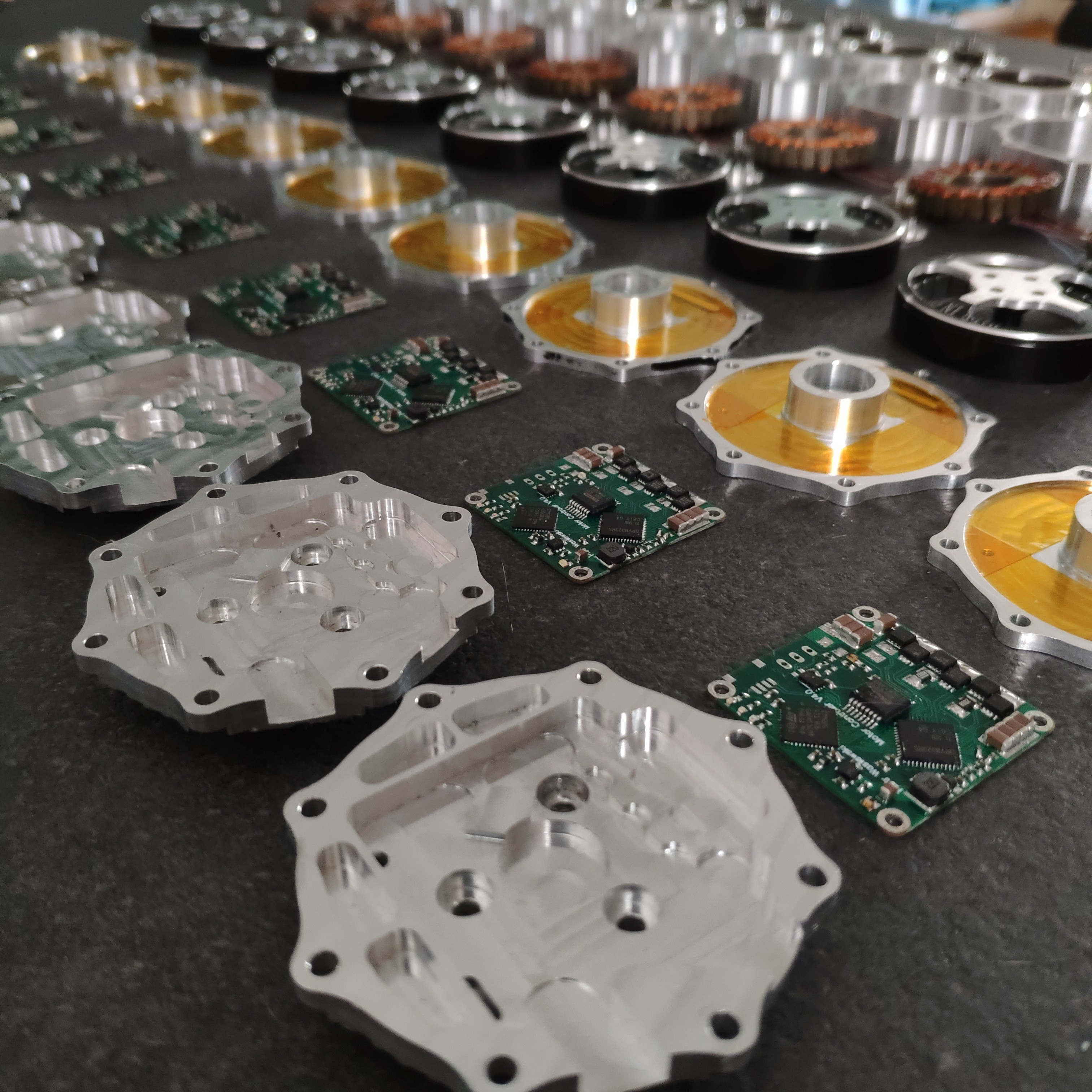
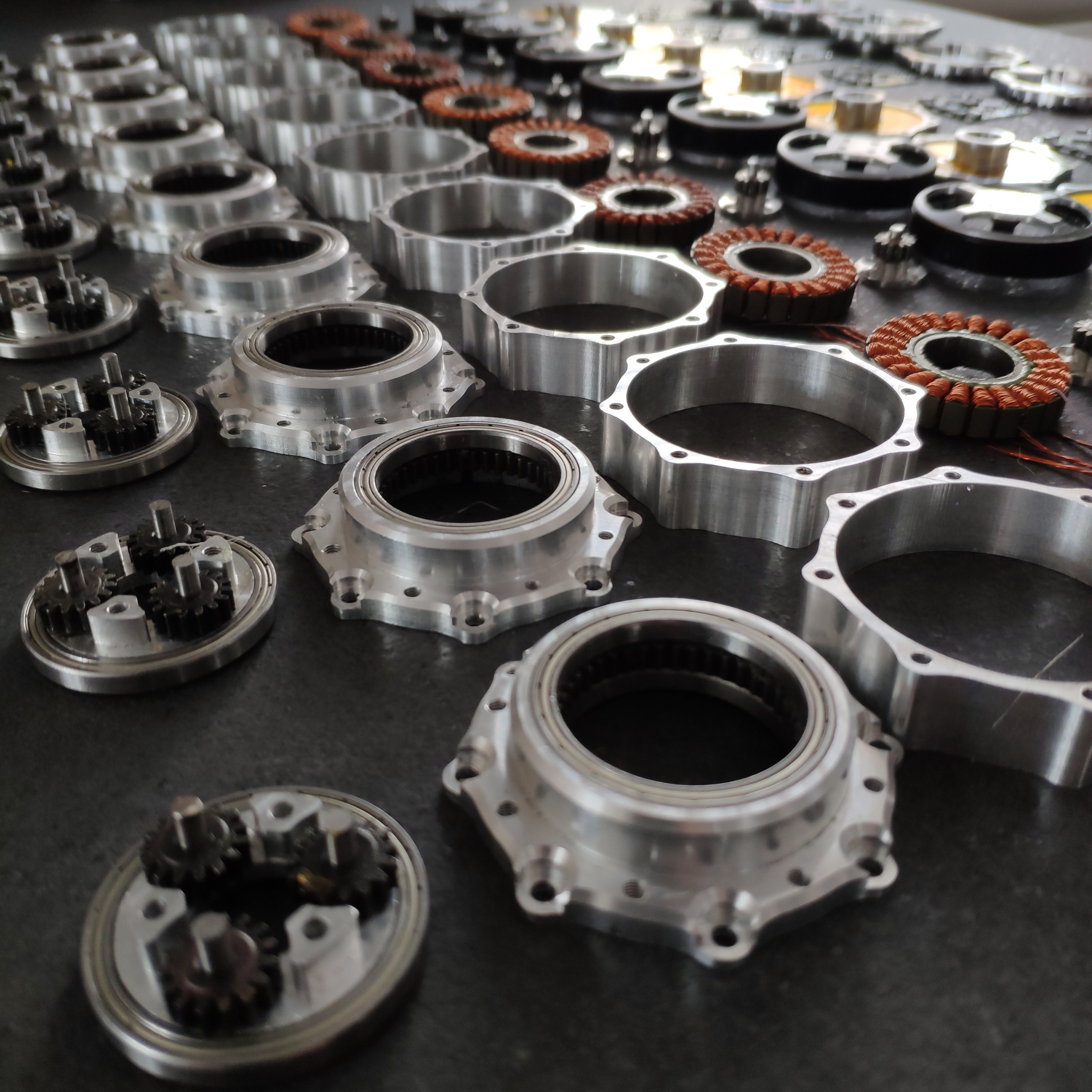
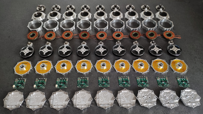
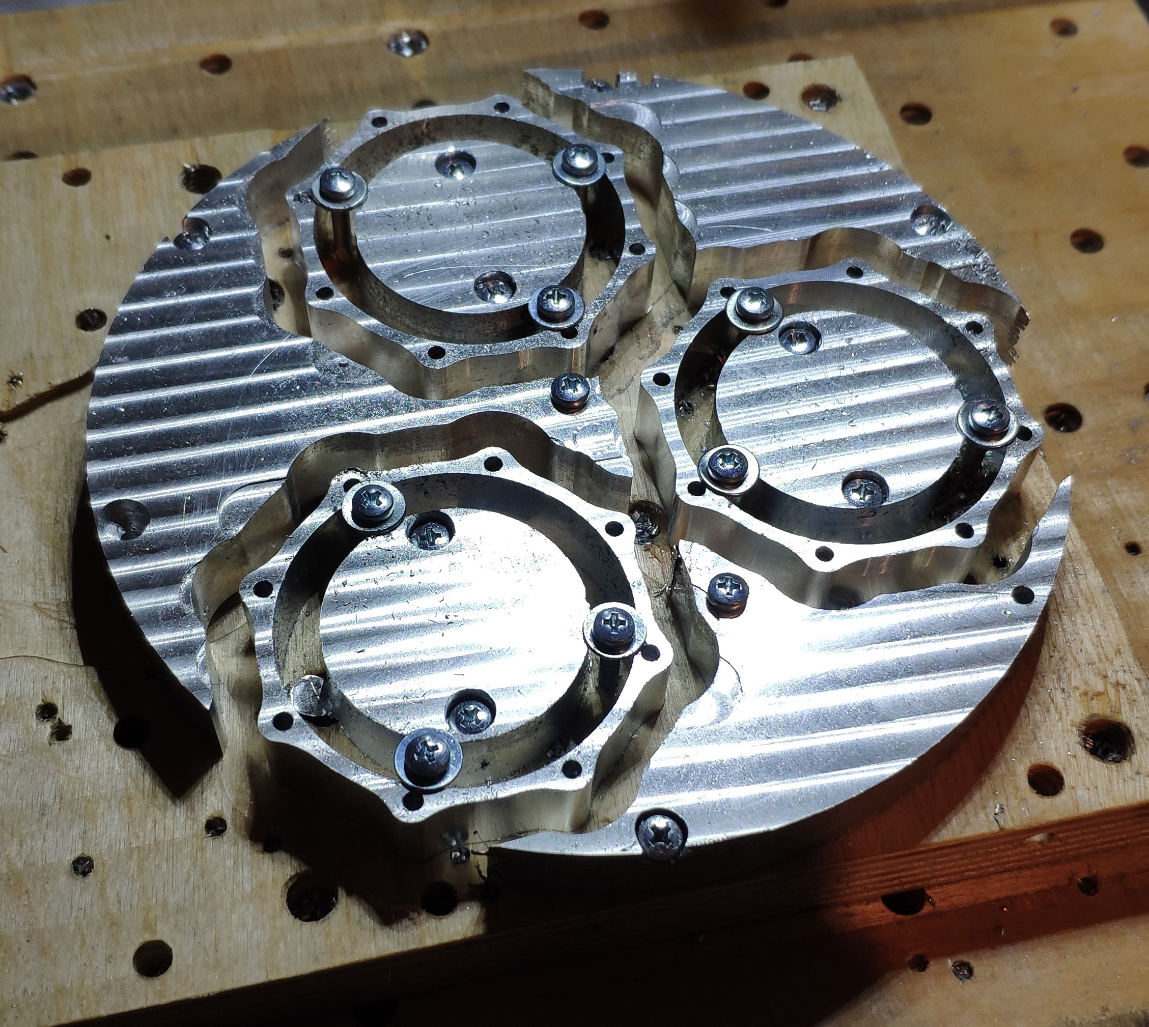
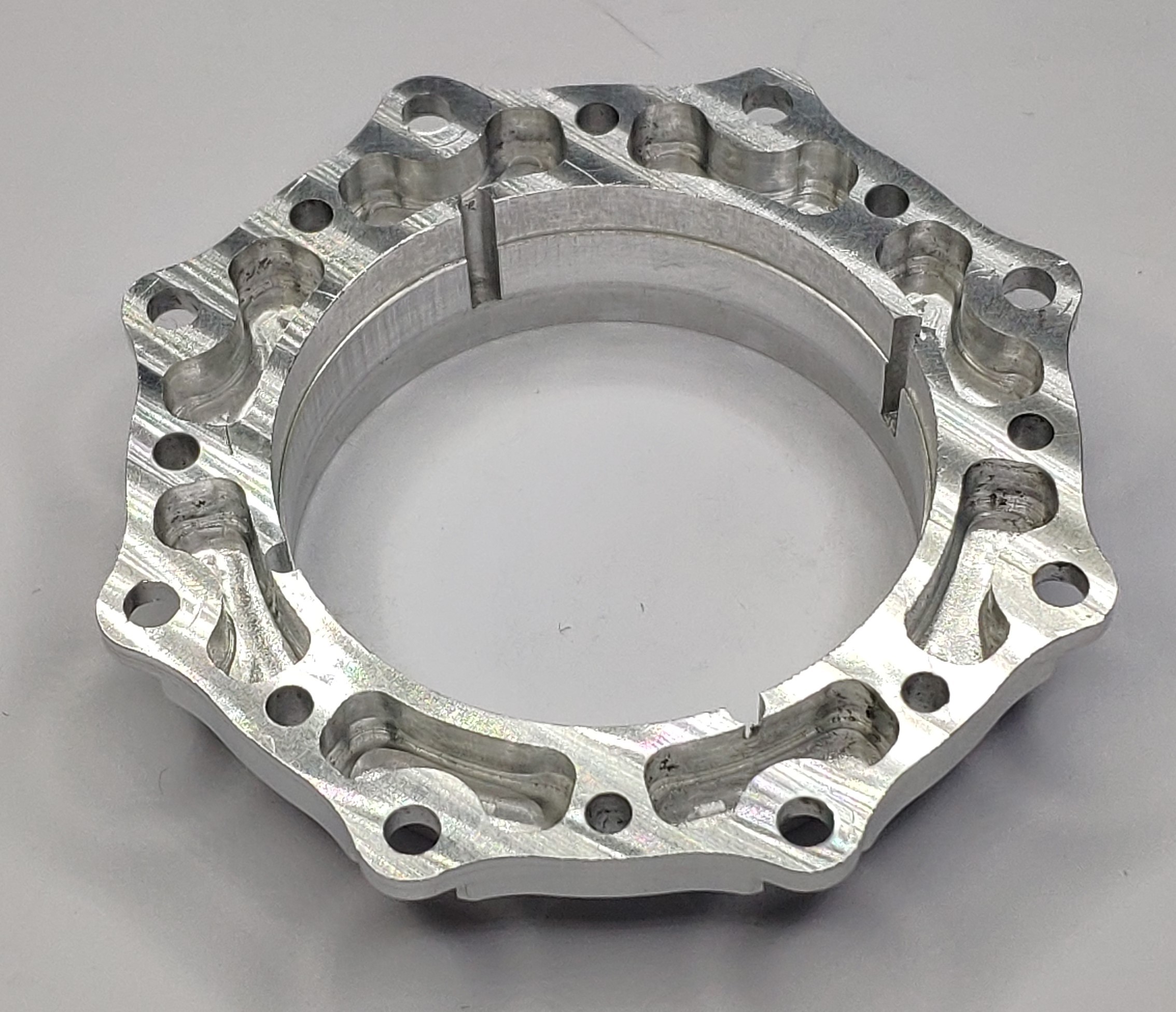
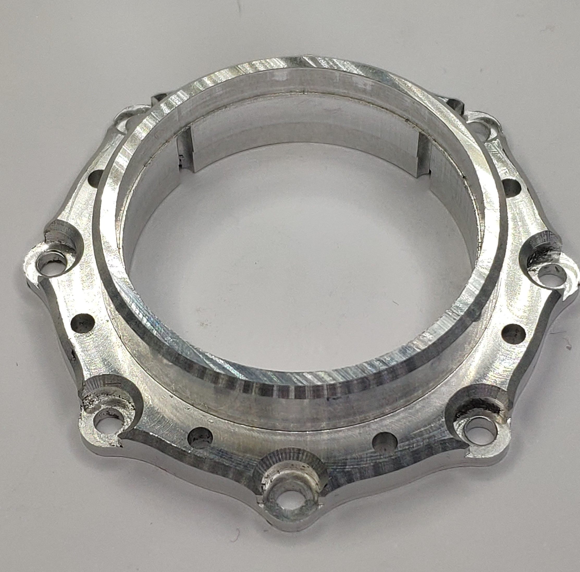
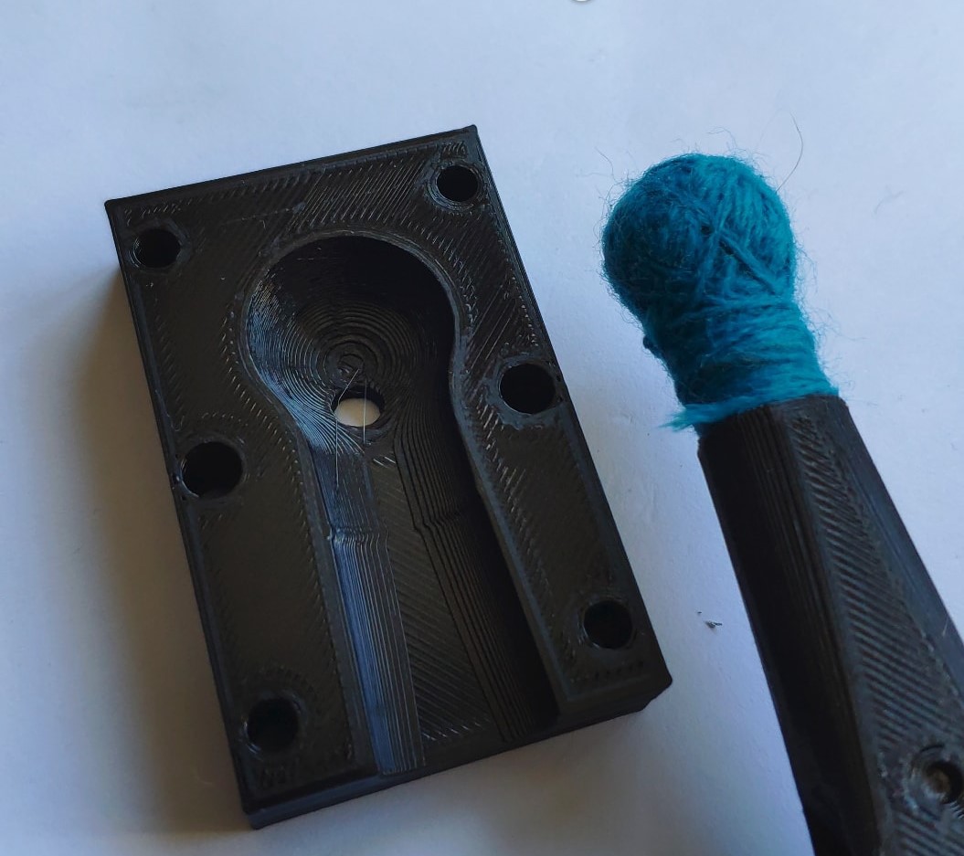
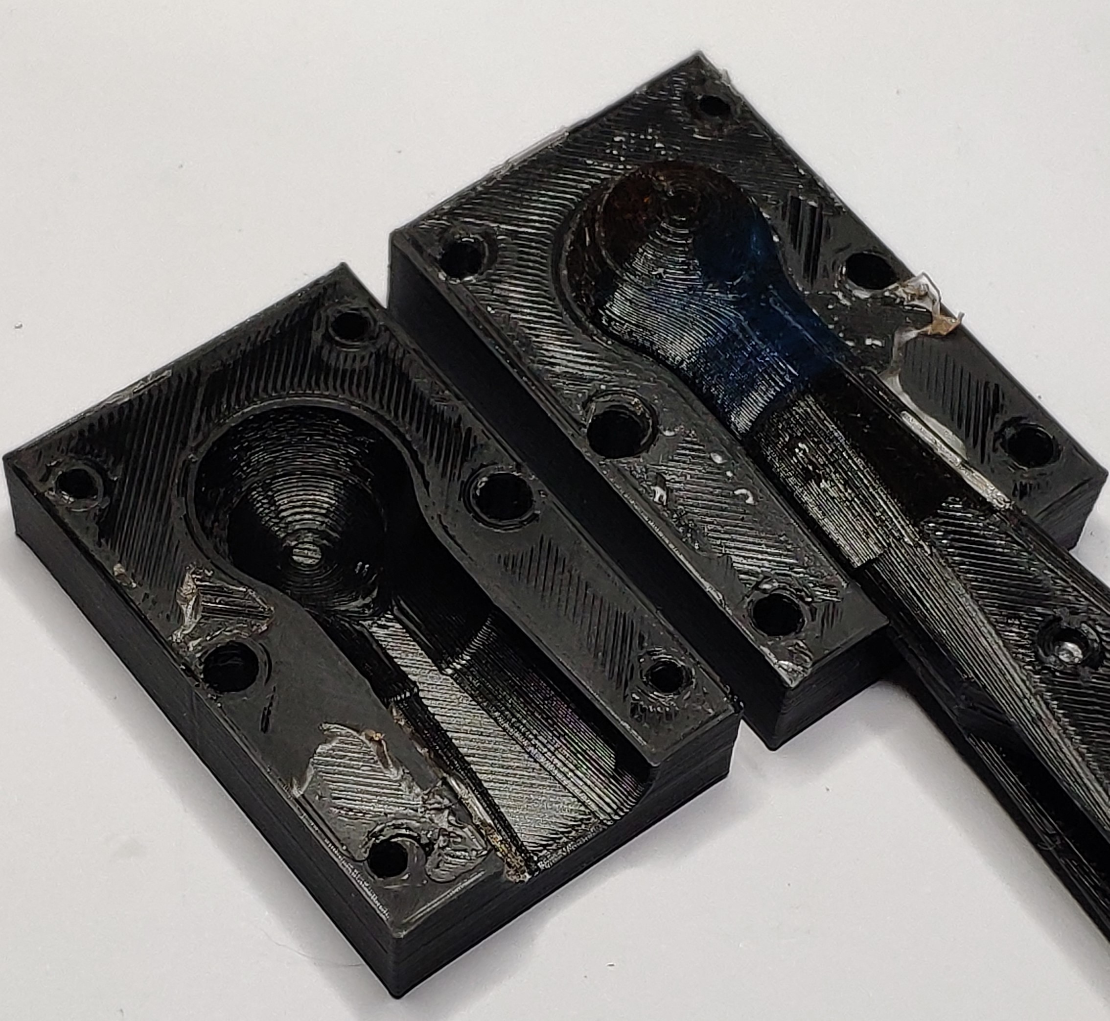
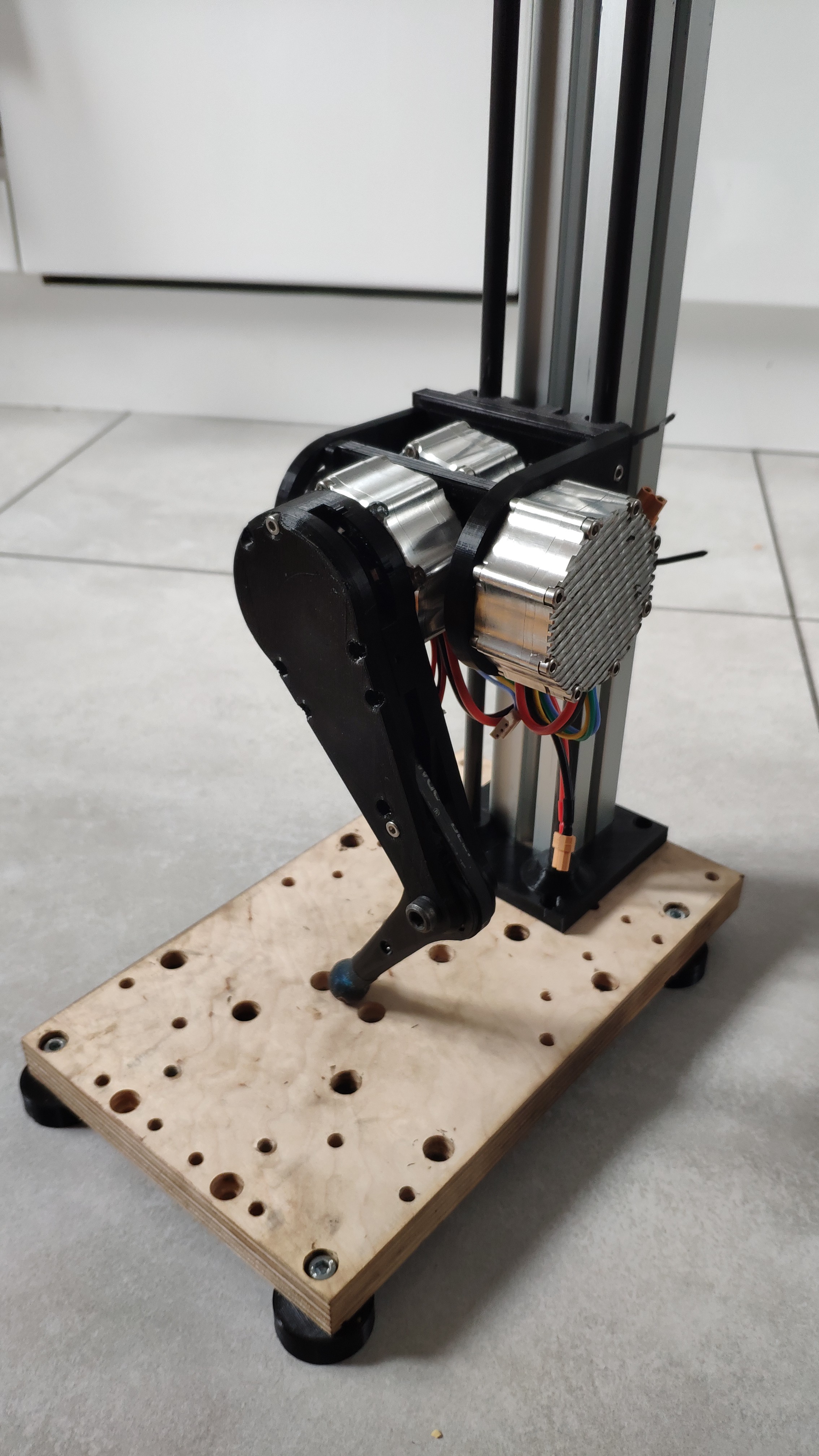
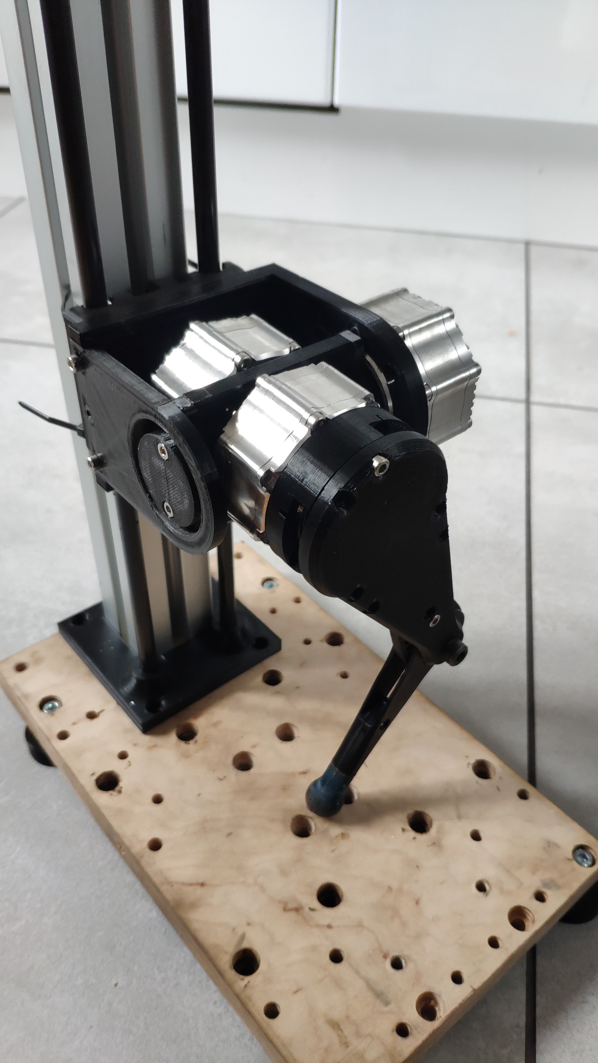
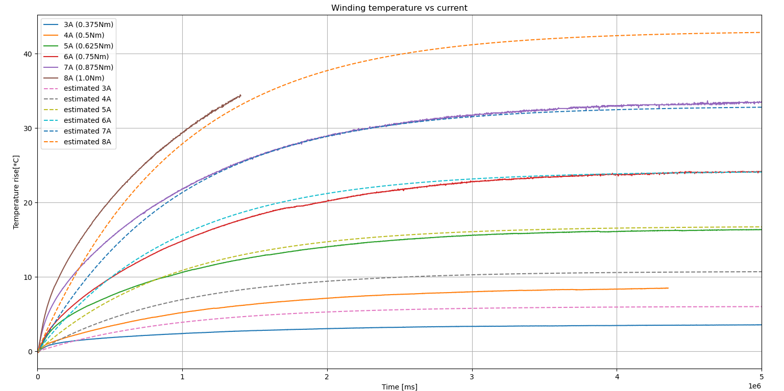
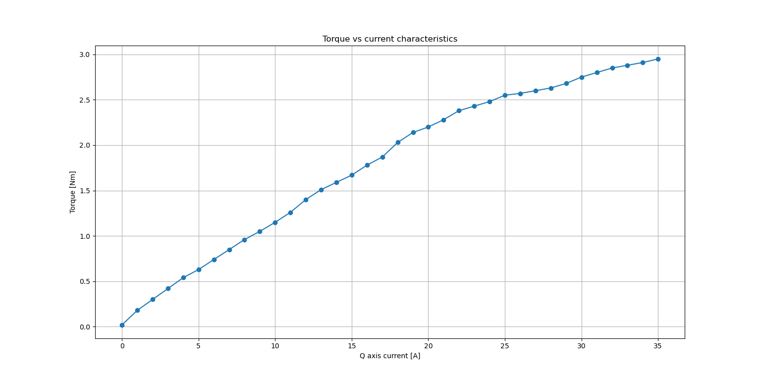
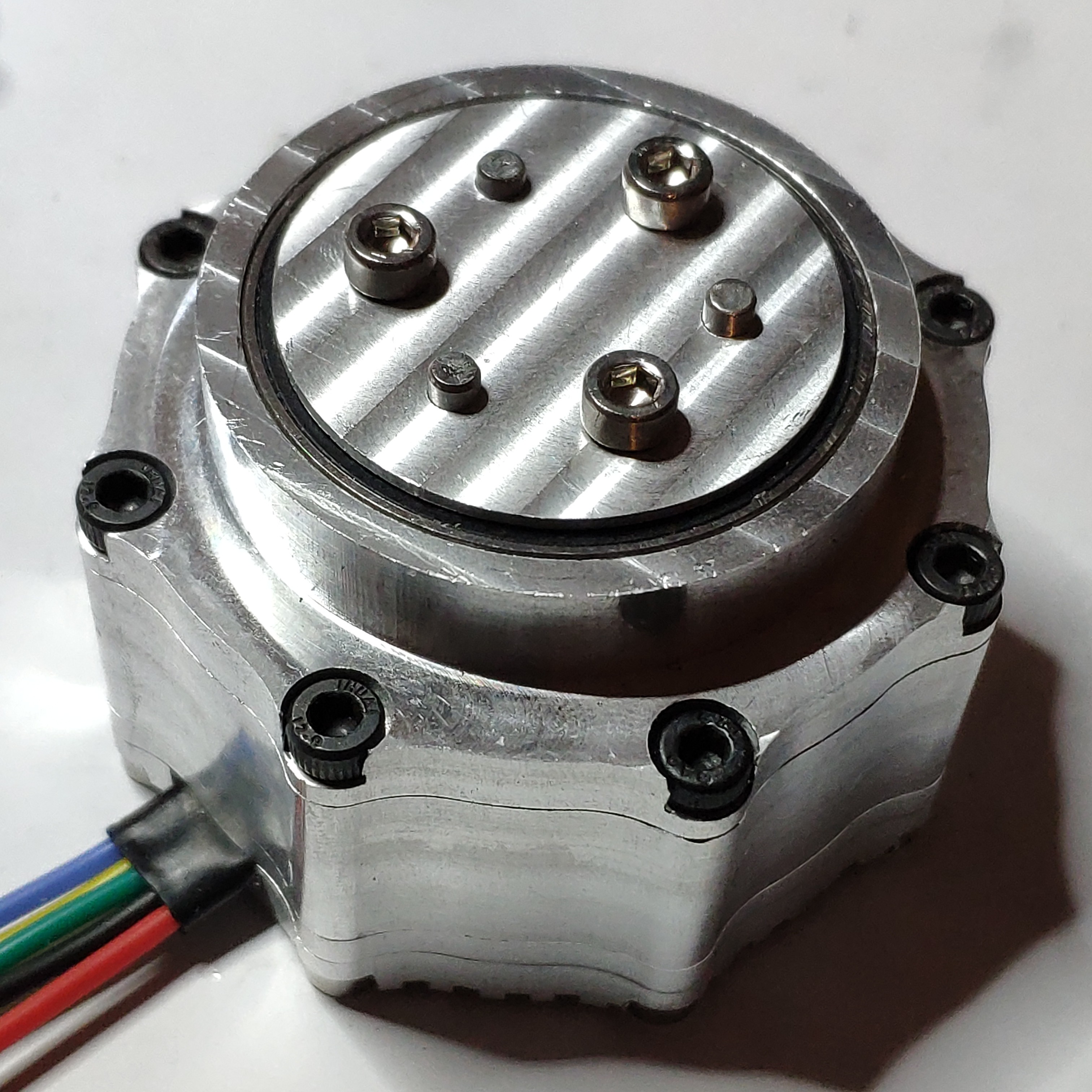
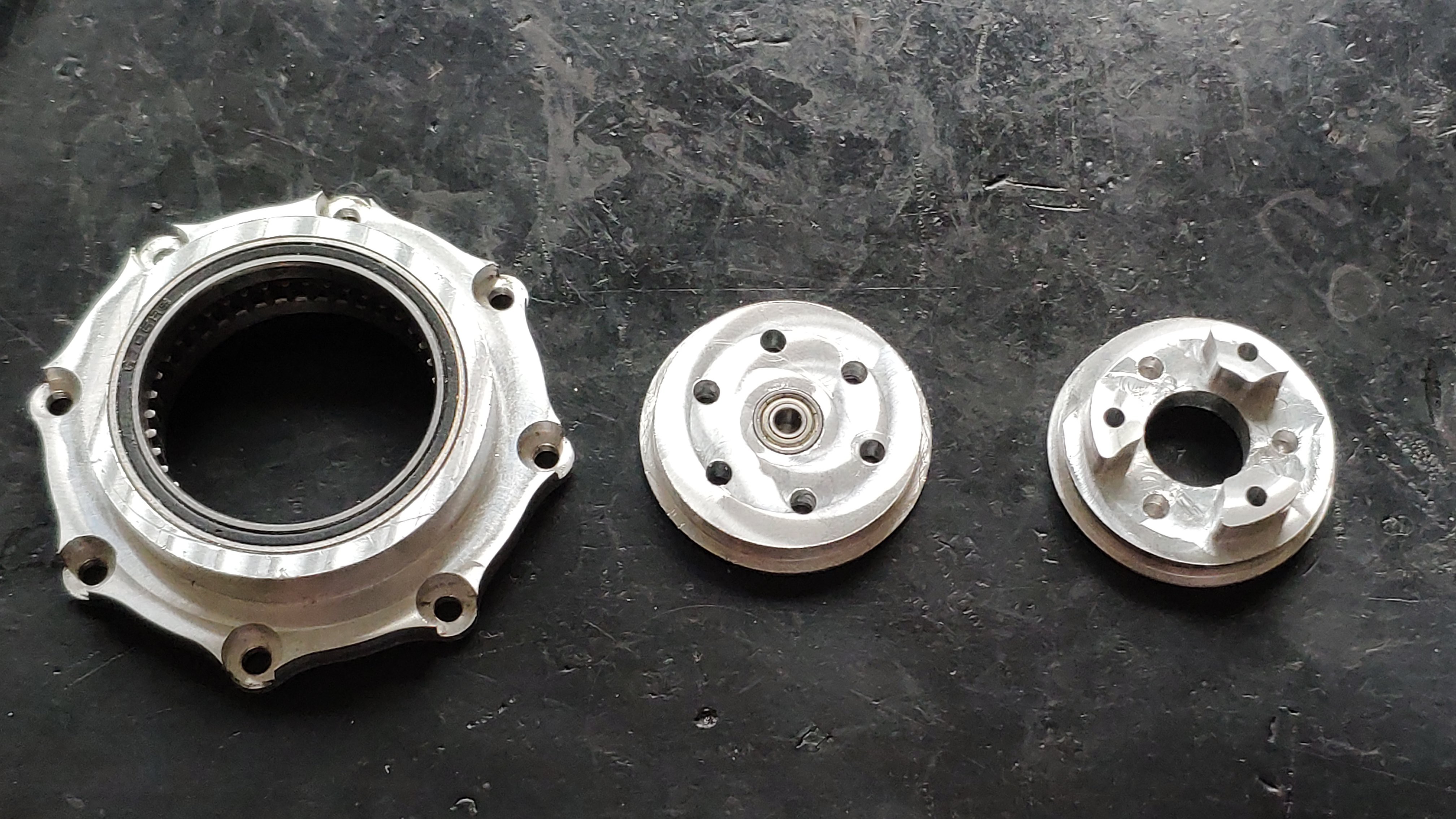
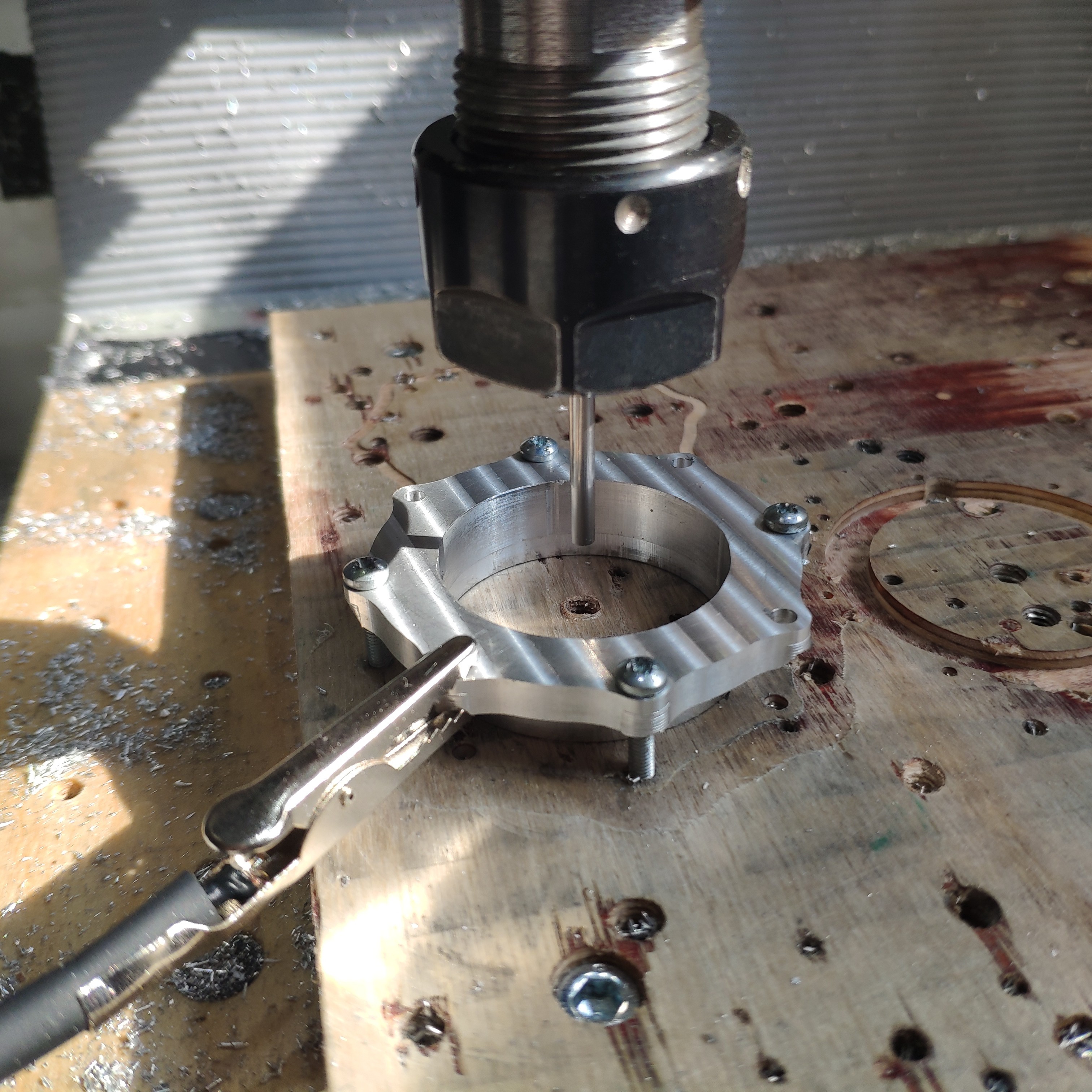
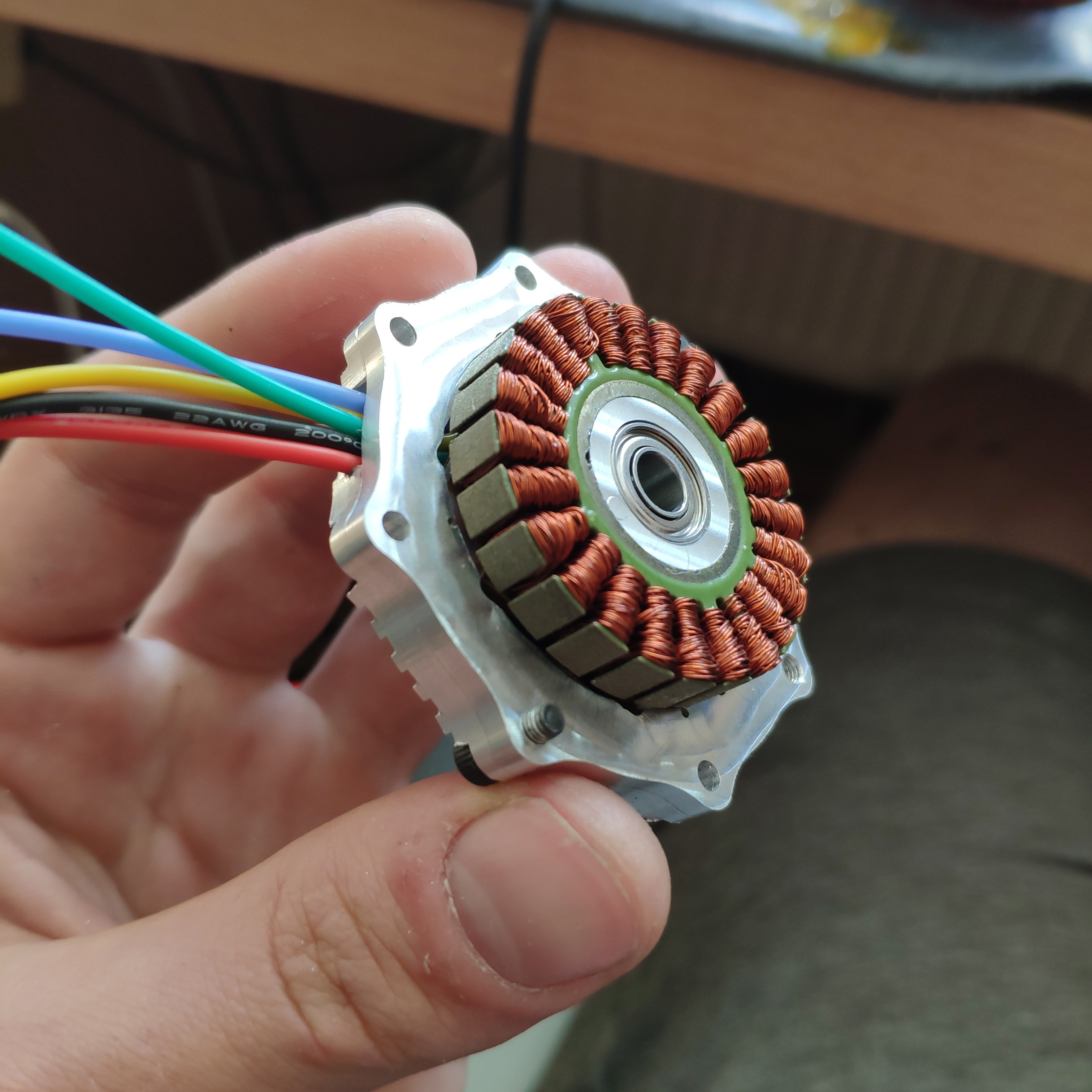
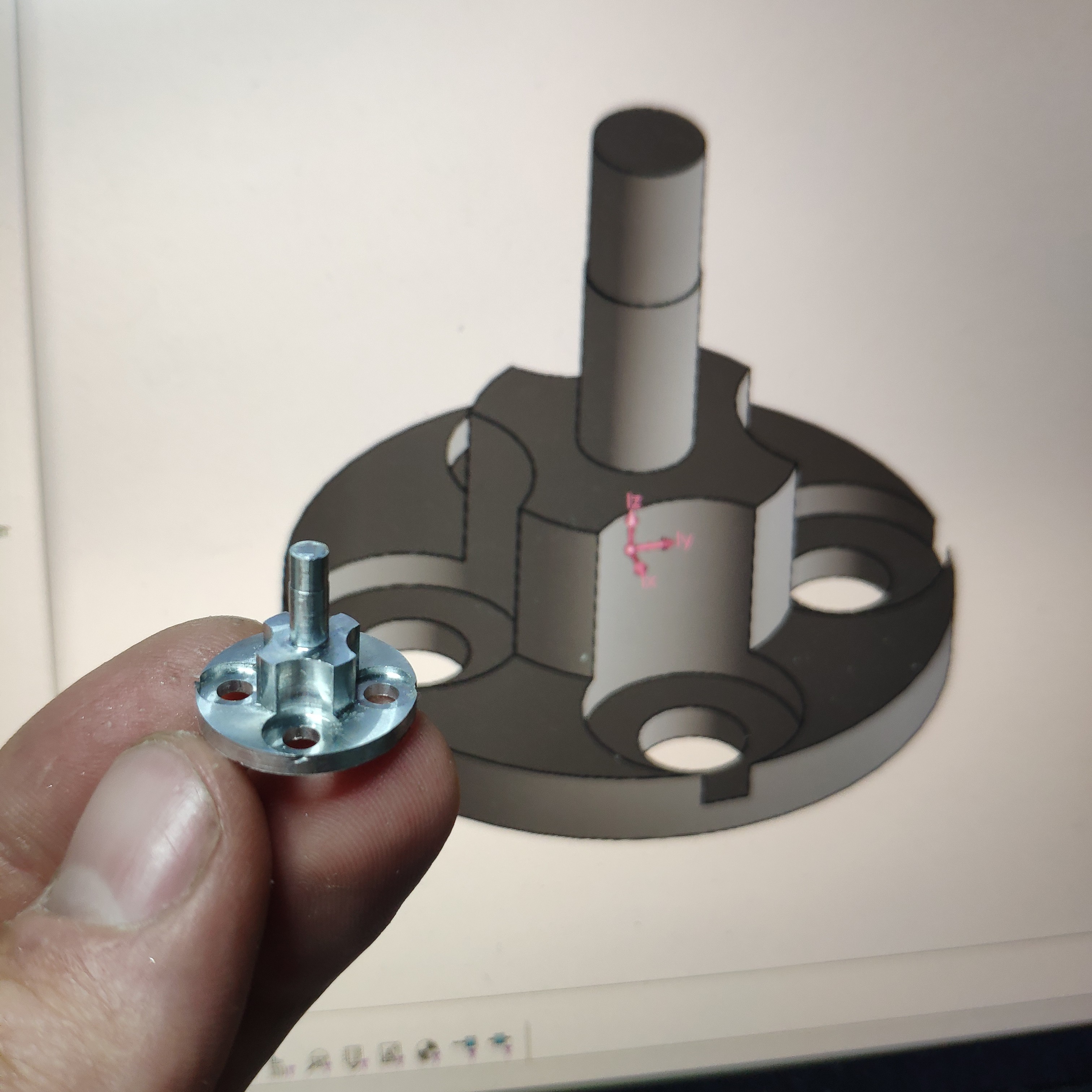
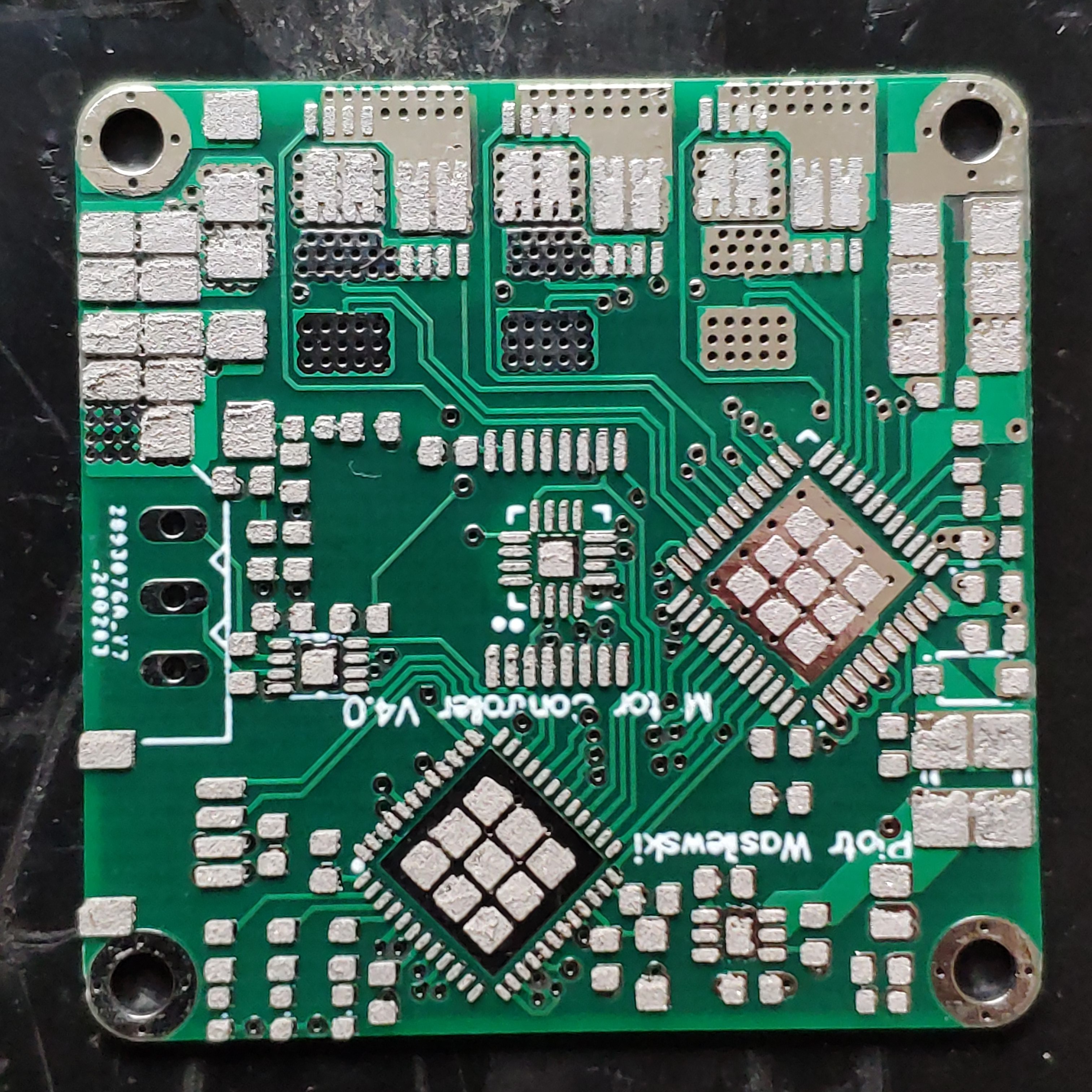
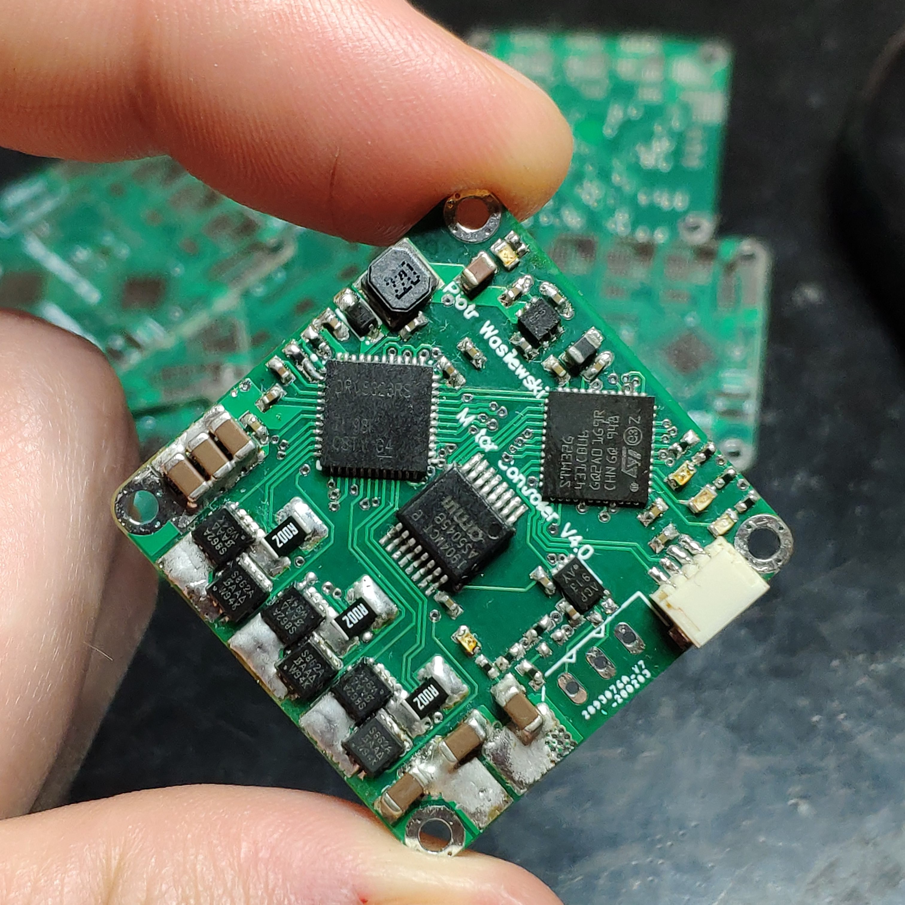
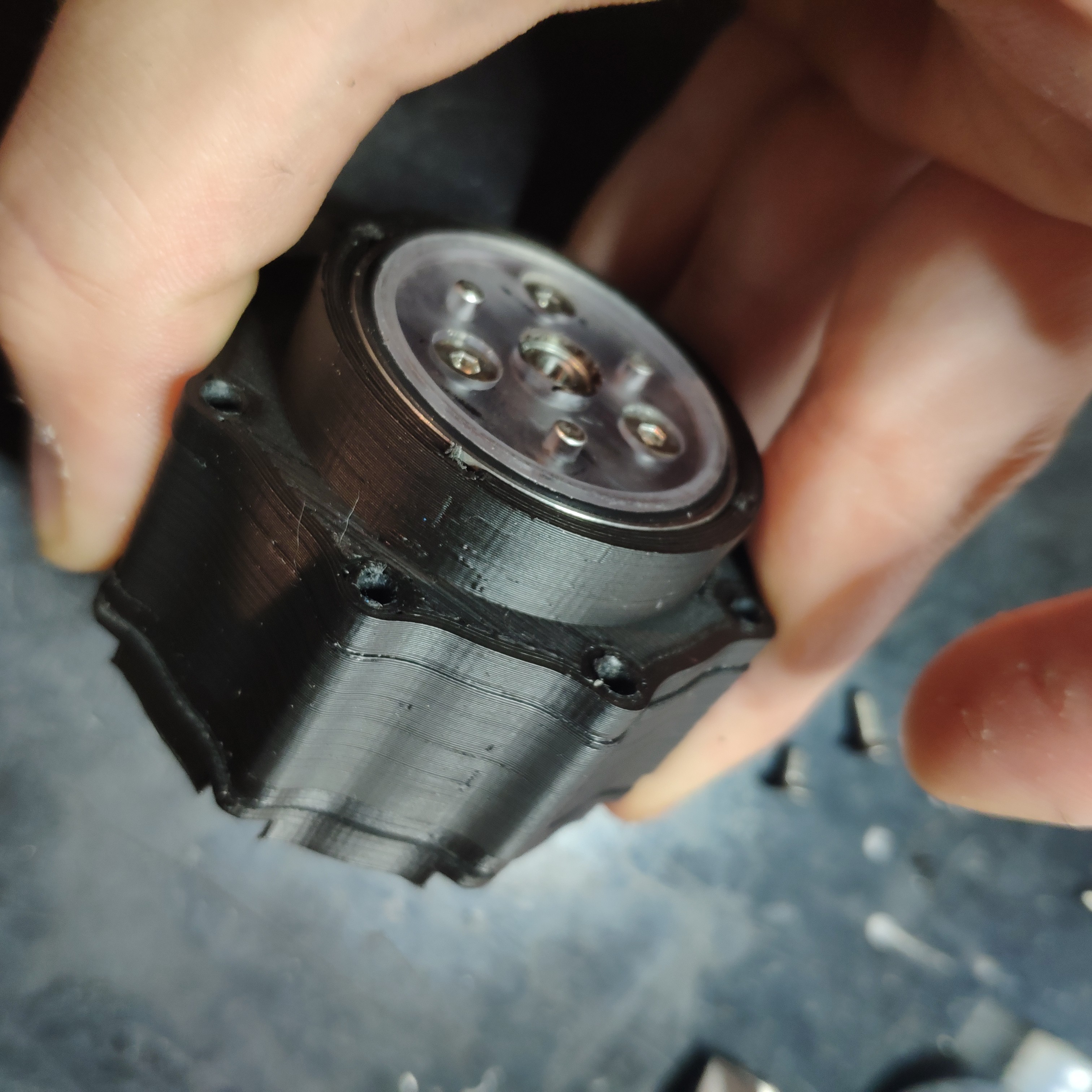
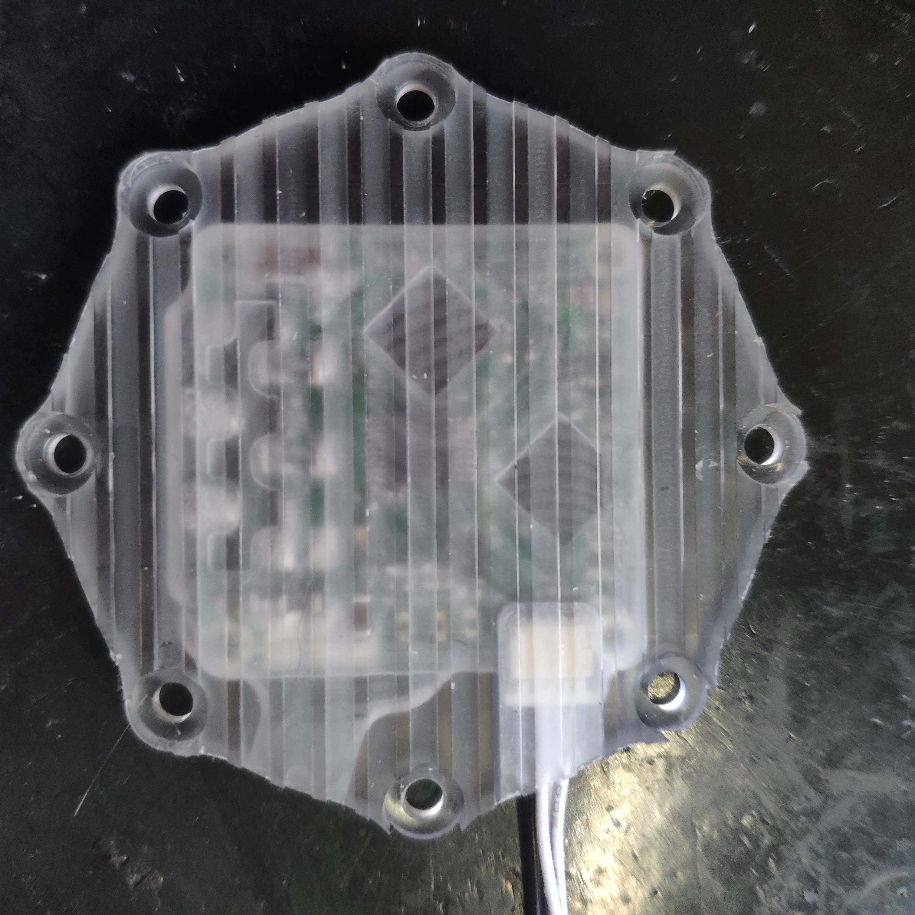
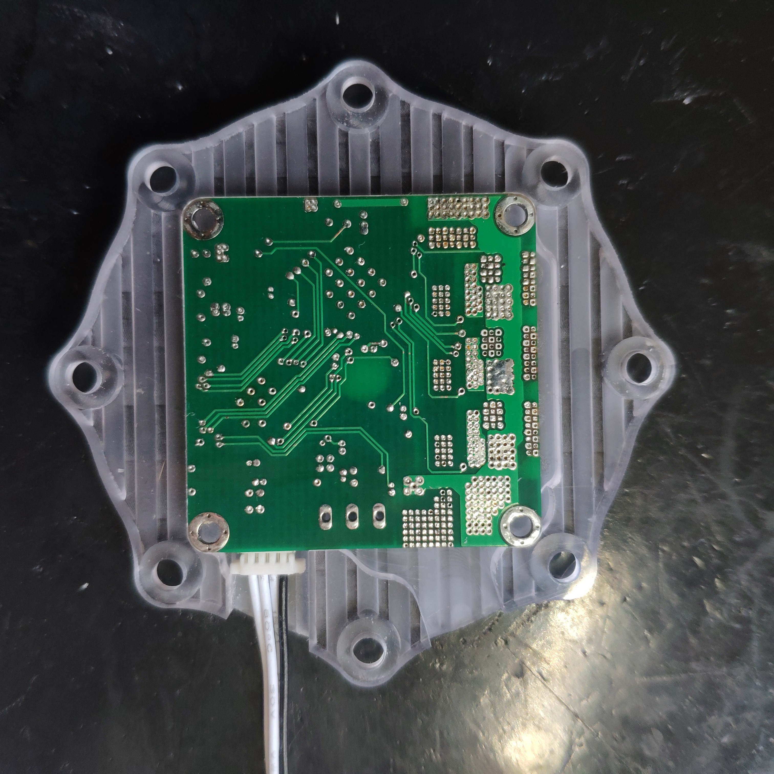
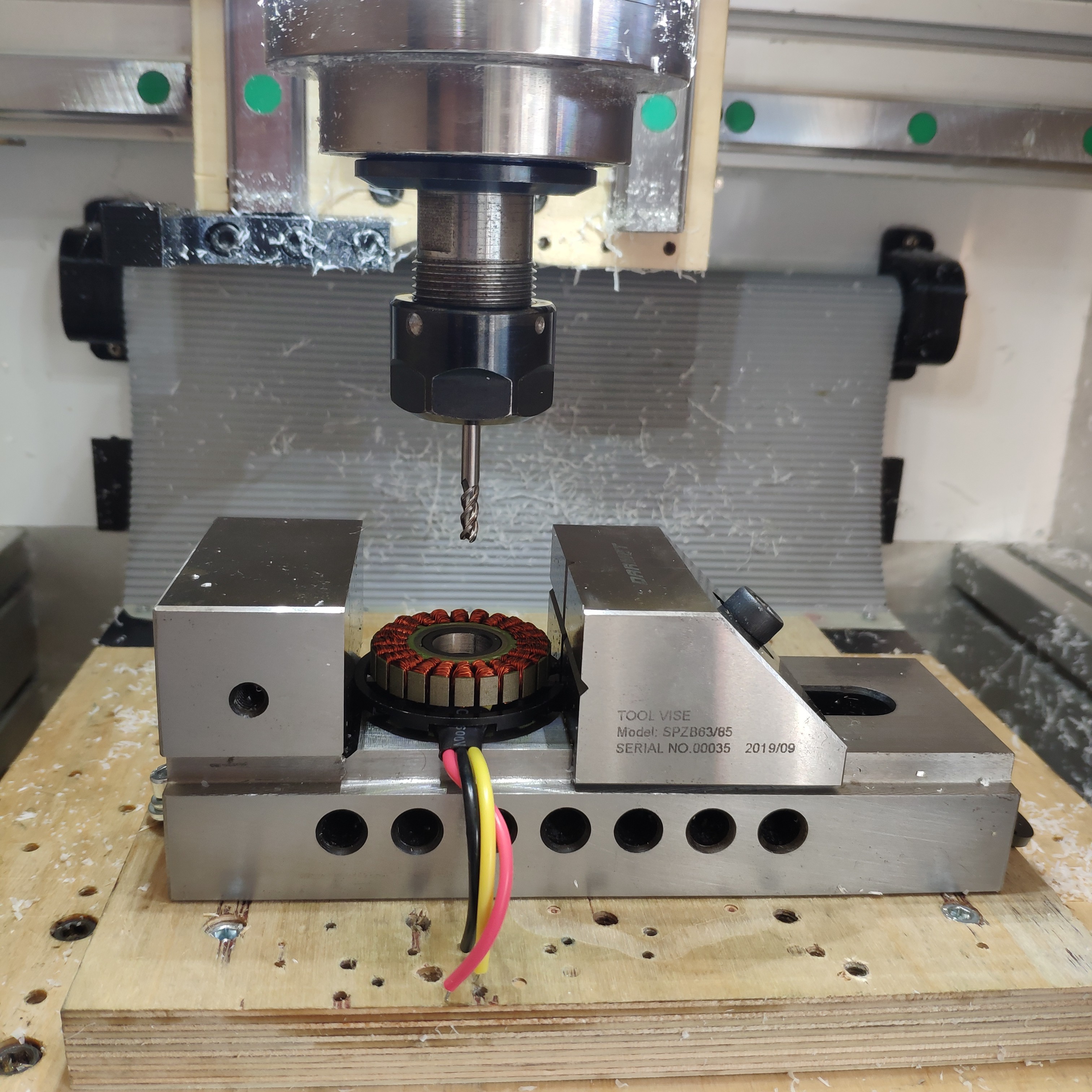
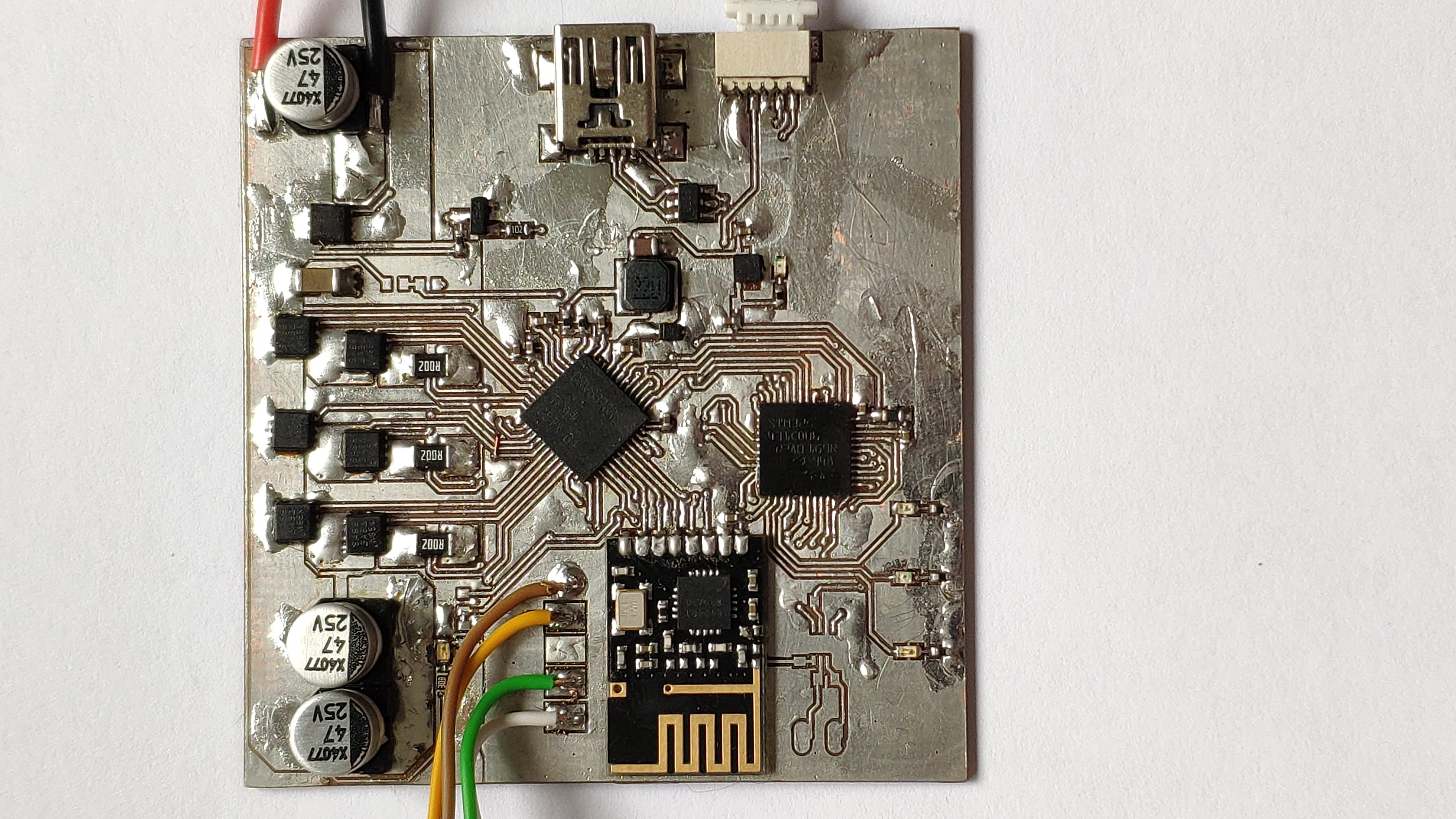
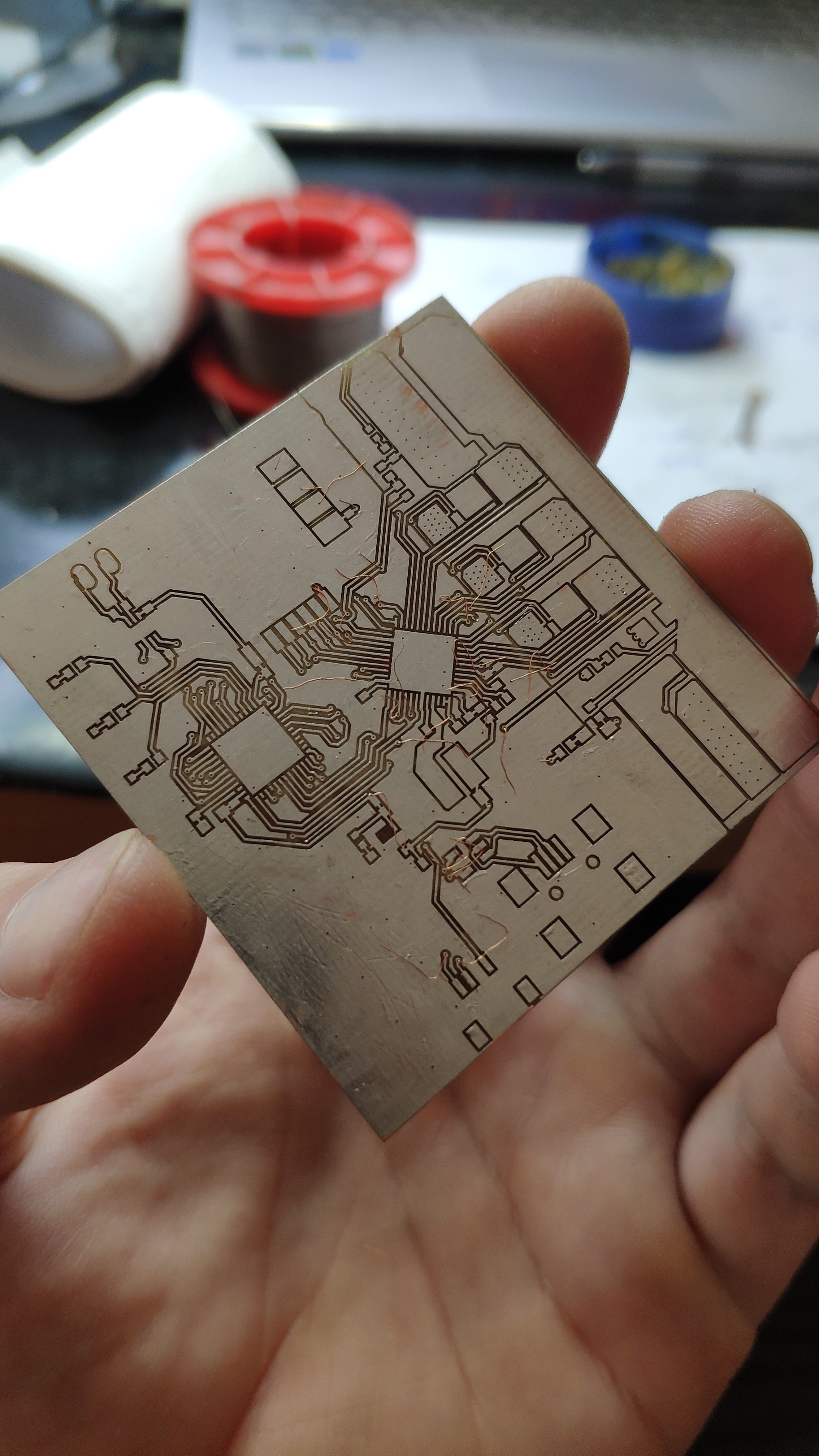
The second version of quadrupedal robot based on custom brushless actuators
 Peter Wasilewski
Become a Hackaday.io member
Already have an account? Log in.
Just one more thing
To make the experience fit your profile, pick a username and tell us what interests you.
Pick an awesome username
hackaday.io/
Your profile's URL: hackaday.io/username. Max 25 alphanumeric characters.
Pick a few interests
Projects that share your interests
People that share your interests


 George Albercook
 Capt. Flatus O'Flaherty ☠
 EK
EK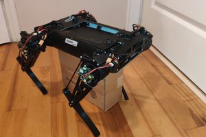
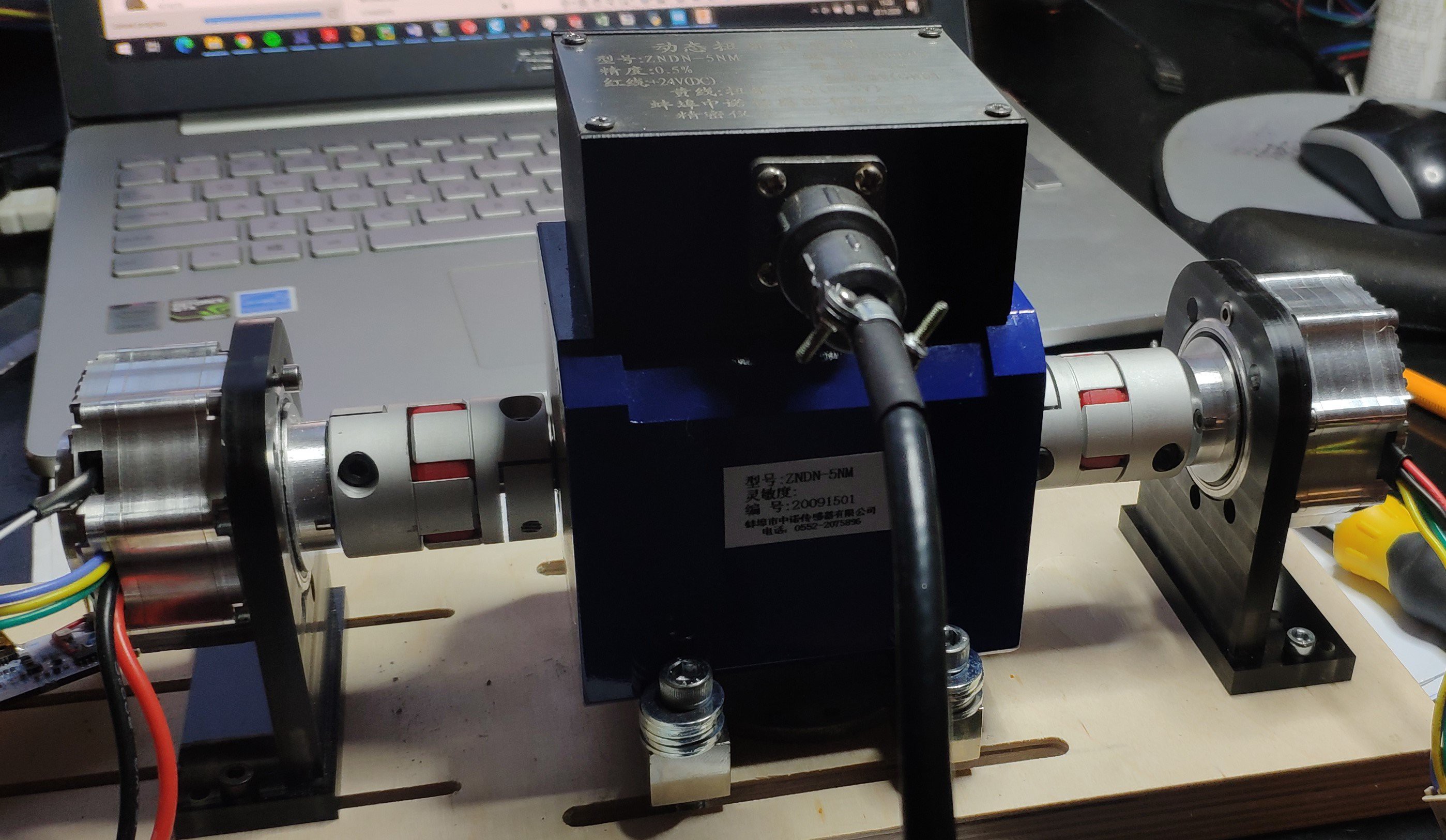
Hey awesome project! I am currently working on a few actuators for robotic arms and robotic dogs and i need a torque sensor. Can you share where you got yours and a part number?