Feature List
- Provide a stable powersupply with short time UPS function
- Backup short power interruptions <2sec. without user notice
- Mechanically stable USB-C powersupply connector instead of micro USB
- Shutdown function using a power button
- No maintenance cost caused by dead batteries
- No risk of fire because the powersupply is using supercapacitors instead of using risky LiIon techology
- Connector for external power button
- Connector for an expansion board with relay & power LED to switch loads without draining current from the supercaps
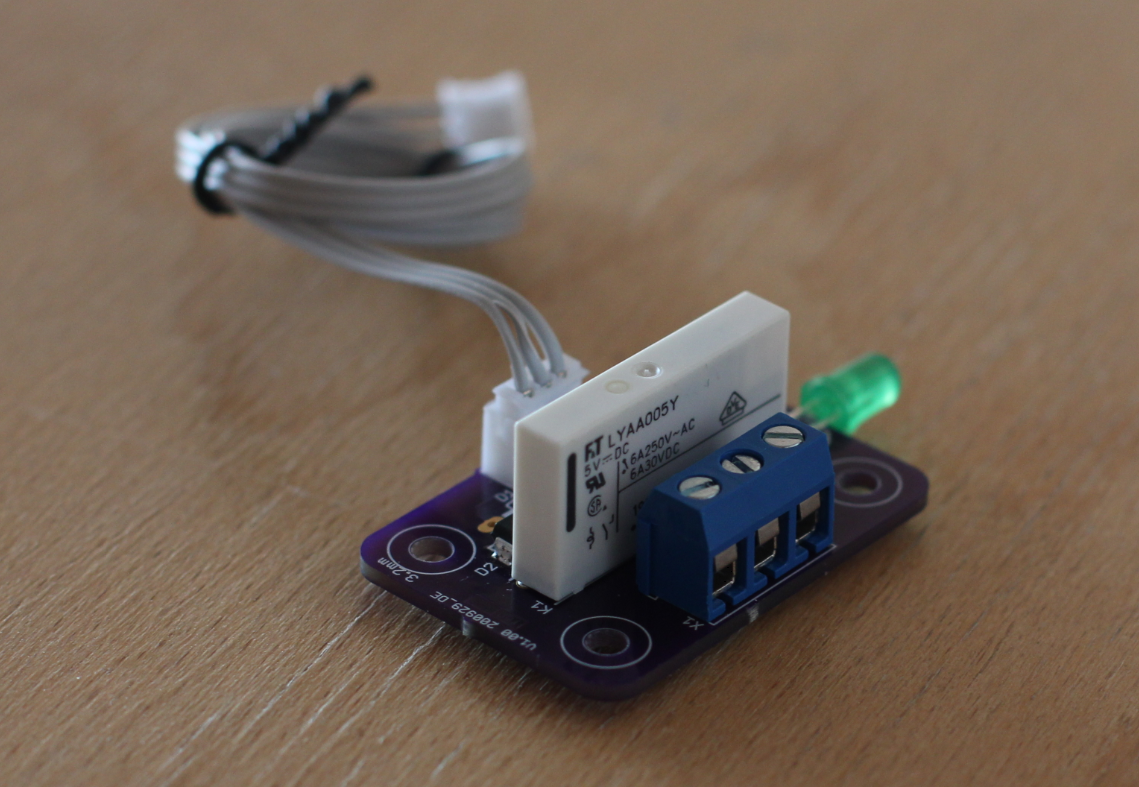
Addon board with
- External power LED
- External relay option to switch high current loads
The UPS function is limited to an operation time of approx. 30..60 seconds. That is far enough for a save shutdown.
The powersupply remembers its last state. It excacly comes up in the last mode it was running.
That means:
- If the device was disconnected by removing the power cord while it was on, it will restart in "on-mode" after reconnecting the power cord
- If the device was off when removing the power cord it will remain off after reconnecting it and can be started using the power button
- If it was switched off by the power button it must be switched on by the power button
- If it was shut down by the shutdown command or via the user interface it will come up if the power button is pressed or the supply cord is (re-)connected
All those functions are available in a PIhat compatible PCB
Initially it was designed for arcade machines but there are a lot of usecases where it fits like:
Raspi based:
- NAS
- Homeserver
- IoT server
I'm using it on all of my raspi computers at home because it is so convenient just to remove the power cord without the risk of corrupted SD-cards.
How it works
The design is based on the supercap charger LTC4041 from Linear Technology. I was following mainly the application note for that chip.
An additional µcontroller is taking care of the interface to the raspi and interacting with the LTC4041.
µController functions
Backup UPS funktion
This is not a really UPS backup power function. It is just to bridge small power outage glitches of < 2s.
Shutdown on power loss
The µcontroller is "listening" to the power fail output of the LTC4041. If it indicates a power fail. The µcontroller is waiting until the backup time of 2s is expired, then it gives notice to the raspi by pulling the power good signal low. After a period of approx. 25s it switches the supply to the raspi off.
Shutdown on button press
If the power button is pressed the µcontroller gives notice to the raspi by pulling the power good signal low. After a period of approx. 25s it switches the supply to the raspi off.
Shutdown using the Linux shutdown command
The raspi is pulling a specific GPIO (24 or 26) low. The µcontroller recognizes it and is switching the supply to the raspi after 25s off.
Remembering the last state
The state of the powersupply is recorded in the eePROM of the µcontroller. This means that after re-powering or pressing the power button it comes up in the same state as it was before switching off the power. A kind of wear leveling algorithm is used to ensure a lifetime of > 1 million switching cycles recoded in the eePROM.
DC Specification (For best performance use the official raspberry pi USB-C power supply)
| Input Voltage | 5V .. 5.2V |
| Output Voltage (Power cord connected) | same as input voltage |
| Output voltage during shutdown | 4.72V .. 4.88V |
| Output current (Power cord connected) | limited by wall plug max. current |
| Supercapacitor charge current | 1A max. |
| Backup time (500mA load current, 25F Supercap) | 60s (theoretical vallue, load will be disconnected after 20s) |
| Backup time (1000mA load current, 25F Supercap) | 25s (theoretical vallue, load will be disconnected after 20s) |
Performance (with 35F Supercaps)
Raspberry PI 3B with official TFT display powered by the official raspberry pi USB-C supply
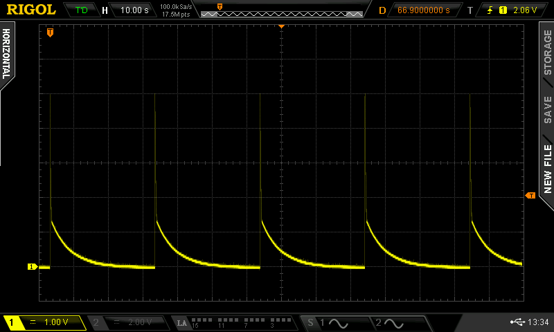
Images showing the shutdown procedure
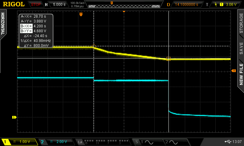
Channel 1 - Supercap Voltage (UPS function works as long as voltage is >2.5V)
Channel 2 - 5V supply to the raspi
To save as much as possible current, the supply to the raspi is lowered to 4.7 .. 4.8V in case it is supplied by the supercaps
Shutdown current Raspberry PI 3B with official TFT
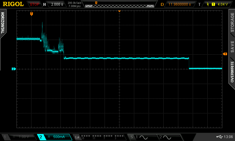
The operating current is approx. 1A. When pushing the shutdown button it takes approx. 4s to shutdown. Then the power consumtion is stable at 300mA. After 20s the power supply is switching off.
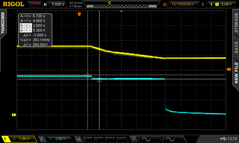
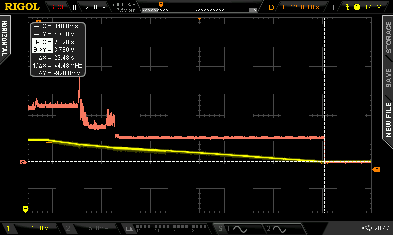
Supercap voltage Raspberry PI 3B with official TFT
Channel 1 - Supercap voltage
Channel 2 - Raspberry Pi current consumption
During shutdown the Supercap voltage decreased by 600mV (4.6V -> 4V) this means there is a lot of margin. Most probably I'll change to 25F supercaps. It is also worth to think about the reduction of the shutdown timeout. 15s instead of 20s seems to be more than enough. Please write your experience with shutdown times into the comments.
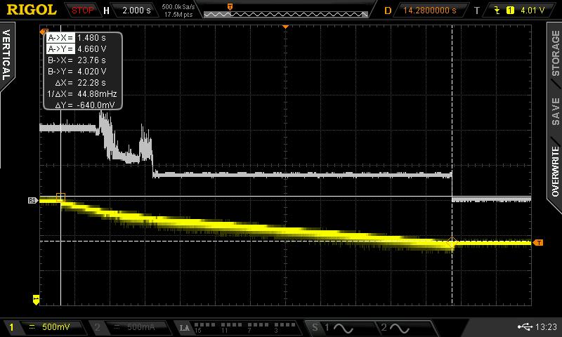
Supercap voltage Raspberry PI 4B 8GB with official TFT
Channel 1 - Supercap voltage
Channel 2 - Raspberry Pi current consumption
Basically this is similar to the PI 3B. Slightly higher running current consumption. THis results in a higher drop of the supercap voltage during shutdown. But with 3.7V at the end of the shutdown cycle there is still a lot of margin.
Again, this leads me to modify the supercap capacity to 25F instead of 35F. This has also the benefit that the caps are a bit shorter in dimesion, so the caps do not hit the LAN connector of the Raspberry Pi board.
Further reduction of the load to the supercapacitors
Connecting all other (5V) loads via the relay expansion board reduces the current consumption further.
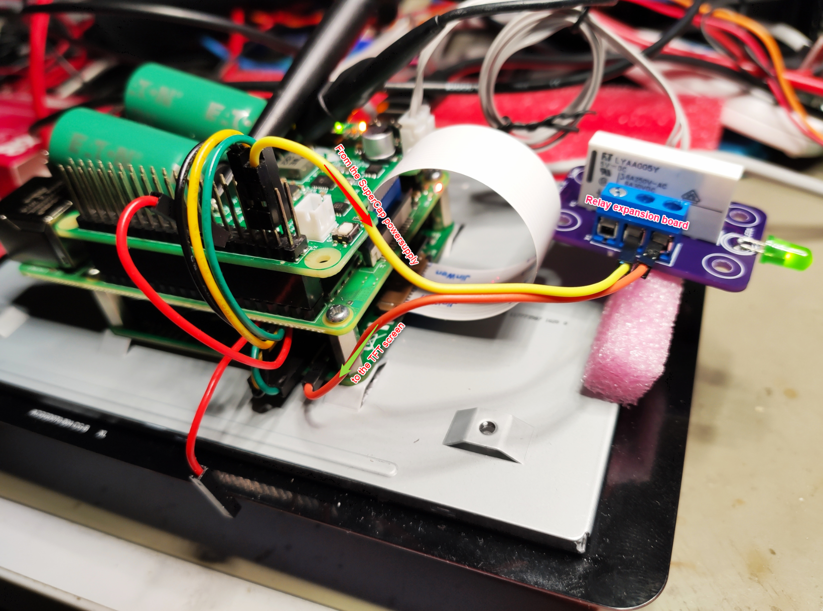
It is also possible to power high voltage (115V / 230V max. 6A) loads via the expansion board.
Voltage drop at the moment of disconnecting the powersupply

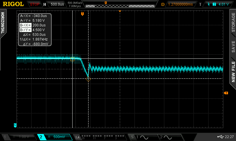
Channel 2 - 5V supply to the raspi.
Pitfalls
Official raspberry pi USB-C powersupply (3A)
Everything worked fine using the power button function or disconnecting the USB-C connector. But when I used my switchable power strip strange things are happening. First the raspi was powered off and then after a few seconds it was re-powered despite the fact that the power supply was switched off by the switchable power strip. This drained the supercaps totally and the raspi was doing what it should not do. It crashed due to power loss.
Measuring the USB-C voltage of the raspi powersupply showed the following:
The switch on the power strip is only disconnecting one wire to the powersupply. The other remains connected. So the supply is getting a kind of powered via the Y-capacitor inside. From time to time if the input capacitor of the powersupply is charged enough the AC/DC converter inside is starting and produces a pulse. This is waking up the µcontroller on my board and causes the malfunction. Unfortunately the time constant of that switching pulse duration is seconds so it cannot be solved by filtering. The only way to have a workaround is to remove the power plug from the outlet or use a power strip that disconnects both cables.
General USB-C powersupplys and cables
It is important that there is sufficient input voltage. It is mandatory, that the supplyvoltage is higher than the minimum supercap voltage which is 4.7V plus headroom for the charging circuit inside the LTC4041. As rule of thumb I'd say at least 5V should be available at the input of the circuit. I checked with several USB-C - USB-A cables connected to a wall plug.
Most of those cables are that bad that there is a voltage drop of 500mV for a 50cm cable.
Despite the glitching (see above) of the official raspberry pi USB-C power supply I strongly recommed to use it because of the low resistance cables and the 3A rating it is far the best I found.
Don't forget the supercap charging current!
The board supplies the Raspberry Pi with unlimited current as long as the wall plug can deliver it. In addition to that the charging current of 1A adds. There is a built in current limit of approx. 3A. That means that if the current to the Pi exceeds 3A minus charging current (1A max.), the charging current will be reduced as long as the sum of Pi current plus charging current is > 3A. This does not mean that the power to the Pi is limited. It can easily exceed this value by several amperes.
This means that the minimum current requirement for the wall plug is 3A.
Raspi Software Settings
Only one modification must be done in the raspi configs:
/boot/config.txt
# If default GPIO3 is used
dtoverlay=gpio-shutdown
# if optional GPIO22 is used use the following dont forget the "_" between gpio_pin
dtoverlay=gpio-shutdown,gpio_pin=22
If the board should be triggered also from the Linux system then a bit of shutdown code is required.
To understand this right. You do NOT need to perform the steps below if you only want power up the board with the button or by connecting the USB-C connector. If you want that the operating system informs the UPS board that it performs a shutdown. In this case you need to add the following steps.
The required files are in the download section.
C-Programs for start & shutdown
Installing Wiring Pi
My copy of Jessie had Wiring Pi installed. You can tell by running this command:
$ gpio -v
If you get something back, it is installed. If you'd like the latest version (or you don't have it installed at all) follow these directions on installing the latest wiringPi.
C-Start.c
This utility runs at startup. It enables a specific GPIO pin as output and sets it LOW. I'm using GPIO26 (which is pin 25(!!) in WiringPi's numbering convention. See below for details.) It only needs user-level privilege. GPIO24 is also possible as alternative pin.
Compile this code and "install" using:
$ gcc c-start_GPIO26.c -o c-start -lwiringPi
$ cp c-start /usr/local/bin/
C-Stop.c
This utility runs during shutdown (and reboot.) It enables a specific GPIO pin as output and sets it HIGH. This must be the same GPIO as used for start.
Compile this code and "install" using:
$ gcc c-stop_GPIO26.c -o c-stop -lwiringPi
$ cp c-stop /usr/local/bin/
systemd services (Raspberry PI jessie and above)
Jessie uses systemd.
powercontrol-comms.service
This service will run c-start during boot and c-stop during shutdown. This is the signal the power controller is monitoring. To install, put this file into /etc/systemd/system. (Note /lib/systemd is meant for system files. Not user files.) Once copied, do this:
$ cd /etc/systemd/system
$ ls powercontrol-coms.service #verify it is there
$ sudo systemctl enable powercontrol-coms.service
# reboot (or install the next one)
Make sure you copy c-start and c-stop to /usr/local/bin/.
Microcontroller Firmware
As onboard µcontroller a STM32l011 is used. The firmware is available via GitHub.
https://github.com/STB3/SuperCapPi
Software description
Basically everything is interrupt driven. Outside the interrupt routine the µcontroller is sleeping.
Three sources of interrupts exist
- Power button
- Power fail/good notification from LTC4041 in case the USB-C plug was removed/connected
- Shutdown trigger from raspberry pi in case the user initiated shutdown via the UI or shutdown command
Each of the interrupts is waking up the unit.
The firmware first checks the interrupt source. Actions will only be taken if the USB-C power supply is connected. Otherwise the new state e.g. from off with supply connected to off with unconnected power supply will be recorded in the eePROM.
The microcontroller knows the following states
enum states
{
    state_undefined = 0,
    ON_powered,        // Unit is running
    OFF_powered,        // Shutdown was initiated by pushing the power button
    APPshtdn_powered,    // Shutdown was initiated by the application SW
    APPshtdn_unpowered,    // Shutdown was initiated by the application SW and later the supply was disconnected
    ON_unpowered,        // Unit was running when the supply was disconnected
    OFF_unpowered        // Unit was off when the supply was disconnected
};
Inside the interrupt routine the previous state of system is checked, the new state will be calculated and actions (shutdown, run) will be taken. At the end of the interrupt routine the new state will be persistent saved in the eePROM. Then the µcontroller goes back to sleep.
To be continued...
This is still work in progress.
License
This project is released under the Attribution-NonCommercial ShareAlike 4.0 (CC BY-NC-SA 4.0).