The e-paper technology looks perfect for periodic update information boards, such as door message sign or a custom weather display. And I want one with an atmospheric pressure graph, but not a little 2-inch display. I want a roomy display to hang on any wall regardless if there is no outlet near it. But a price for a decent size display such as 7.5” seemed still more than I was willing to pay, especially since I would like to put them in a few rooms. I already bought a few small displays, but I couldn’t find a good use for them. Meanwhile, every time I went to my local hardware store, I saw a big two-color E-paper display on every appliance. They looked like a full-blown solution for my use if I could get my hand on it. The device could not be costly, including the wireless interface, batteries, and a case, if they can have hundreds in every store just as labels. Thus, I took a picture of the back of the display and did some research.
The store is using Chroma 74, Black and Yellow, Electronic Shelf Label. The yellow would be perfect for the sun on my weather display. The “74” stands the screen size, 7.4” and the size is almost identical to the Waveshare 7.5inch E-Ink sold on Amazon. It also has the same display resolution of 640x384. I probably was not the first who had that idea, but I could not find much on the web. The display is sold to retailers only and has a proprietary wireless interface. I was able to find the FCC certification with the internal pictures. The display cable and electronics matched a typical Waveshare E-Ink connector and circuit sold as a module on Amazon, plus a microcontroller and battery. Those displays do have good documentation and Arduino libraries. Encouraged by this find, I turned to eBay to see if I can get some. There were a few sellers with a surplus of brand new units for ~$12 (plus a few bucks for shipping). So I got a few. With decades of professional embedded design experience, how hard it’s going to be?
Chroma74 units came quickly and looked perfect. I was hoping I will be able to get the display part number and download the datasheet. Then I will connect to an ESP32 through the E-Ink HAT, and I’ll be done. Unfortunately, too often, things are more challenging than they initially seem. I found the display part number (WFD0750BF19) on the display cable. It was Wuxi Vision Peak Technology Co. 7.5 color display, but I could not find a published datasheet. The datasheets for other smaller modules were available, so I had something to try. The big surprise was that the display connector was epoxied to the controller board, unlike the FCC pictures. It’s not surprising that they glue the connector. It’s not only cheaper, but it is less prone to vibration. Additionally, the cable had reversed pinout (or up-side-down connection). The unit contained a single PCB with four sections and a set of six 2450 batteries in parallel. Per the unit brochure, they will power the display for five years – talking about efficiency.
To see if there is an easy path, I decided to connect the display to the E-Ink HAT with a generic e-paper Arduino sketch for a 7.5” display. The connector was unglued with a lot of heat and patient. One wrong move and the cable would be damaged. The extra epoxy was cleaned with alcohol. The display’s flat cable was too tin, and I glued some thin plastic to match the regular connector thickness to ensure a good connection. The Waveshare E-Ink display HAT extension socket allows top or bottom connections; two steps forward, one step back. The glue connector has extra width to provide a glue surface on both sides. The sides needed to be trim to fit into the socket, but there is very little room for error. The connector has a 0.5mm pitch. With all the surgery behind, I connected to a generic e-paper HAT and the controller. No surprise, the display did work. I verified that the busy signal was responding to some commands, so I was sure I communicated to the display controller. It looks like the display is using the IL0371or IL0373 controller. Unfortunately, I heard a buzzing noise from the display circuit. When I plugged my small e-paper display, everything worked, so control was still good. And I didn’t hear buzzing with the small display. Step backward. At this point, I needed a few days off this project.
The fact that I could hear the buzzing made me compare the circuit components on the E-Ink Waveshare HAT and the Chorma74 e-paper controller. Plus, I had a design reference from the IL037x e-paper controller datasheets. Many e-paper circuits are remarkably similar, almost like there is only one design used by several manufacturers (or maybe there is only one manufacturer). After an hour of checking, it seemed the components are very close in values, and the circuit should work. I went back to my initial thought to trigger a splash or test screen. Maybe a low battery or an error if I short the external flash will force a message. I studied the processor datasheet to see if I can use one of the test points. I found pins which are connected to internal serial peripherals and connected the scope. I try to establish serial communication but no luck here either.
I went back to the E-Ink HAT strategy. I tried all different start-up sequences used by other e-paper modules. Nothing worked, but the display is getting darker on one side. Did I fry the display? I went back to the controller datasheets; some had more details than others. I downloaded all the available documents and studied them. One of the display types made the corner of the display flip white and black. It was a corner outside the visible range, but it prompted me to write a simple update profile instead of using the internal update sequence. Bingo! I have the screen kind of blinking. I need a proper profile to drive the update sequence. Not much help on the web again. The Chroma 74 had an external serial flash memory. I dumped the serial flash contents and crawled through it to see if I can find the display factory profile code. The profile has a pattern that I should be able to recognize if written as a table. No easy find here. At this point, I moved step by step through all possible options and crawled slowly forward.
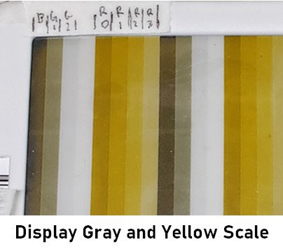
After a few nights, I was able to drive the pixels correctly and display an image. I could draw the image in 3 shades of back and 4 shades of yellow. Almost yellow, I could never get the yellow as deep as the units in the store. There is a fine line when attracting charged particles. If you force it too hard, adjacent pixels will start to move also. If you don’t wait long enough, you won’t get good contrast. I wanted to ensure that fine black graph lines are crisp. I experienced how hard it would be to make a single profile to work in all cases and environments. But my goal is to have my weather station mounted on the wall; the sun doesn’t need to be that bright.
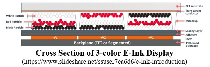
You can find a lot of description on the web about how e-paper technology work. (See: e-ink-elektra-3-color-display). The principle is simple; you drive the electrostatically charged particle to front or back by applying a voltage between the display’s front and back. The display has transparent metal electrodes arranged in rows and columns. In the 3-color display case, the color particles have neutral polarity (and could be a little bigger). Those particles move slower through the medium, and you need to push them with other charged particles. I had trouble understanding how the internal sequencer i.e. the LUT (Look-up Table), manipulate the electrodes and how the update frequency works.
The e-paper controllers are generic and should work with any type of display surface. The controller needs to know how to drive the rows and columns to provide a clear image. There is a lot of variables, such as fluid dynamic and electrode capacity. The sequence is not as straight forward as all black go forward, then all-white move backward. The display has large hysteresis, and you need to move particles a few times back and forth to get a clear contrast. Working with the sequence/profile, I realized that each pixel is represented by four bits, but only 3 bits are used. After an image is downloaded to a controller memory, the controller is requested to refresh the screen.
The controller runs the full sequence/profile based on the LUT. There is a LUT sequence for each of the eight-pixel values and one extra to run the common plate. The common LUT table provides information on how to drive one side of the plate rows, and the other side columns are driven by the specific pixel value based on the LUT tables. The LUT table specifies if the plates should be energized and in what direction (positive, neutral, or negative voltage). The LUT table for this controller has over 200 slots in multiple segments that can repeat. The segments have numerous dive and duration options.
Custom profiles provide a lot of flexibility to do interesting effects. For example, suppose you have four pixels with values 0, 1, 2, and 3. You can write a profile to energize 0 value pixel to push (repel) black particle backward; value 1to push (attract) black particle forward; 2 to push black forward then backward for a short time, and neutral for pixel with value 3. We will end with a white pixel, black pixel, gray pixel, followed by no change pixel. Thus, we can update only a section of the display. This is a very oversimplified profile.
Many displays have the LUT table already preprogrammed (OTP). The profile is designed to work at different temperatures, humidity, and over the display’s lifetime. I could not activate the internal LUT on this display, but I have created two profiles: one for fast white and black update and the other much longer to display grayscale and colors. Do I need the sun to be yellow? Do I need a long refresh time to clear any resemblances of the previous image? It was a very educational and painful exercise.
For the previous few weeks, I had the setup wired and powered up on my workbench. I had just a few hours at night a week allocated to sink into this project. But now, with renewed hope, and the display working beautifully, I unplugged the USB cable. The next step was to figure the power budget so it can run on batteries. After I repower the device, the screen was not working. Another step backward. It seemed like I went back to square one! I worked for a few more hours, but I was not able to get the display working. I walked away for a few days; I was too frustrated. It appeared that I put the device into “a working” mode by moving through sequences for different displays. At this point, I did a hundred permutations. I want back to my notes to recreate “the working” setup. Divide and concur. It seemed that I have to run initialization twice with two different profiles. Without actual display datasheet and spec timing, those were only my guesses, but it works reliably after each power-up. Please, no more surprises. I want to claim victory.
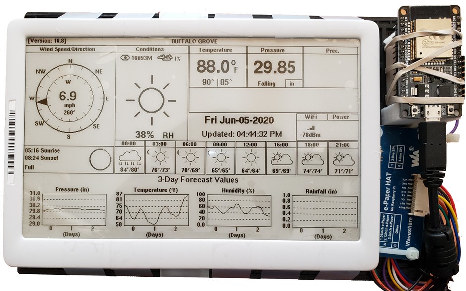
With the ability to display an image, the next step was to try the weather sketch and see how long I can run on a set of AAs. A huge thanks to David Bird for providing the Arduino ESP32-e-Paper-Weather-Display library (“https://github.com/G6EJD/ESP32-e-Paper-Weather-Display”), impressive work. I update the GxEPD2 Arduino library to drive the Chroma 74 display and successfully run the 7.5” weather sketch. Unfortunately, with all my efforts to low ESP32 power, I could only run a month on a set of two AA with updates every 30 minutes.
I found others were struggling with the ESP32 sleep power consumption. The unit took a much higher current than the datasheet values. I remembered an article on Hack-a-day where a person used ATTiny as a power control for ESP. I had some ATTiny85, and I follow the suggestion for now. The goal was to stay as long as possible inactive and minimize the active state, especially the WiFi period. The web has many articles on ESP power saving, but unfortunately, ESP tri-states all pins during sleep mode, and I need to wait for a while for the display to finish the screen update. An interesting suggestion to minimize WiFi connection was to use a static IP to speed up the connection time. To shorten the controller’s active time, I decide to put the ESP in full sleep after the request to refresh the screen and not wait for the screen to finish the update. This shortens the active time to 2sec. The ATTiny waits predefine time until the display completes an update and entirely cuts power to the display and ESP processor. I added two-way serial communication between ATTiny and ESP. Before the ESP goes to sleep, it tells ATTiny when to provide the power again. ATTiny internal timing is not very precise, but it doesn’t need to awaken it precisely in 30 mins. Now the unit should run over six months on three AA or one rechargeable 18650. Time will show.
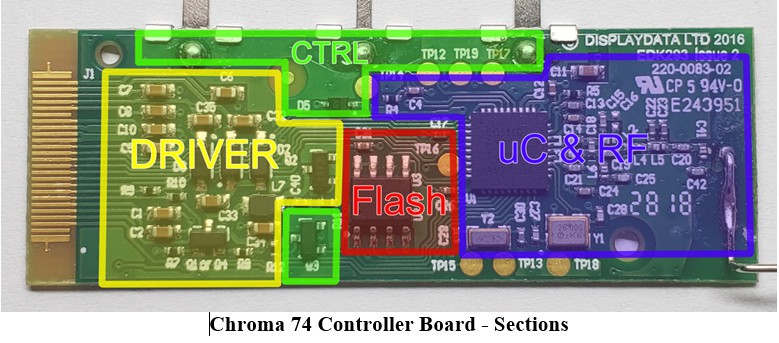
All the current work was done as a proof of concept on the bench with external E-Ink HAT. The next step was to make the wall unit and claim the victory. Before I was going to build the second, I decided to use the display with the driver on the original control board. The E-Ink display HAT costs $15. This is more than I paid for the display with all the extra stuff! Plus, why should I risk breaking the connector while removing the epoxy? How hard can it be to reuse the driver on the board? The controller board has four sections: a TI processor CC1110 with an RF section, an external MXIC 25V8006E - 8M flash chip, an E-Paper driver (which is almost the same as E-Ink HAT from Waveshare), and a power switch for the display.
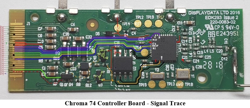
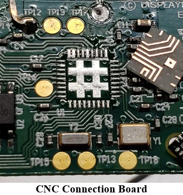
From the beginning, I decided not to engage myself with CC1110. I seemed like another distraction with its own set of adventures. I chose to solder six control wires and two power wires from the ESP32 controller (plus one to control display power). And again, no easy way; those traces had no test points! But there is six processor programming test pad; if only I could bridge some of the processor pins. So I blindly jump to trace the signal line to the processor and to test pads. Then, I could use my CNC router to make myself a tiny PCB bridge board. Then I would lay it copper side down and use a hot air pencil to solder it. So I did; an hour later, I had a tiny board. Too bad that I had not desoldered the processor before I did the board. The processor had the solder ground pad underneath. I should know it, but I was blinded by my great idea. At least I had some fun with my CNC.
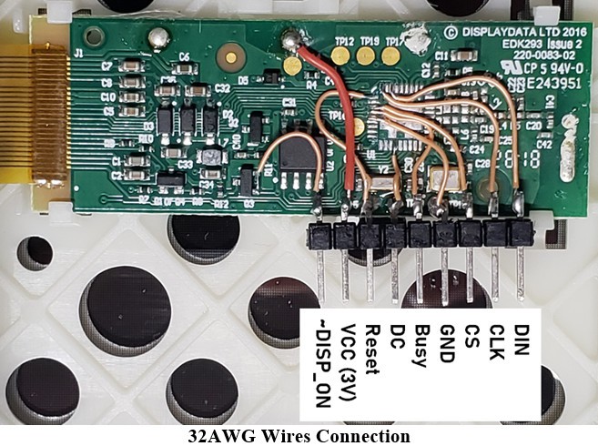
Since the board had not reasonable test point to solder wires, I soldered directly to the VQFN36 process footprint pads. It was possible with solid 32AWG wire but took a steady hand a strong drink. With practice, I was able to make all connections with 10 min. I have used three programming pads to secure a standard 2.54 header.
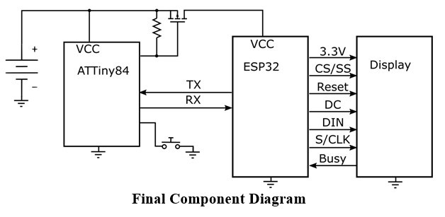
Below is my final diagram with battery voltage monitoring and a manual update button. ATTiny sends the battery voltage, the power-up count, and a button state to ESP on power-up. The button can trigger a weather update, over-the-air code upgrade, or configuration mode. I decided to use ESP32-CAM modules for now because they are cheaper than ESP32 bare modules. If I decided to make more of those units, I would use an ESP32S module with a custom PCB.
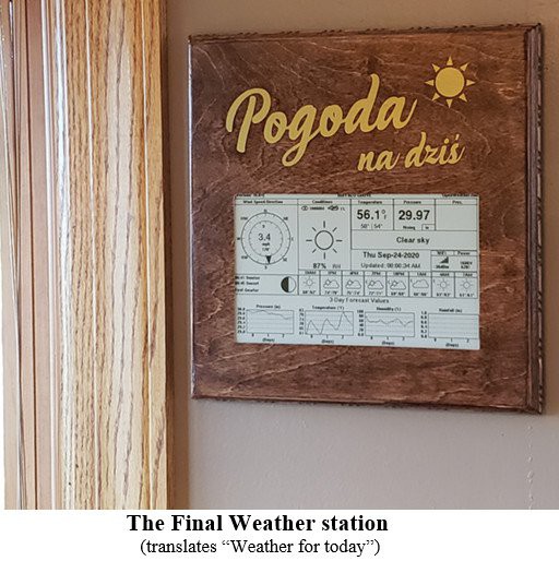
With all the challenges behind me, I had the weather station wired and programmed. I made some small modifications to the weather sketch and changed the update profile back to black and white to maximize the update speed. My full-color profile can take up to 20 seconds. In the future, when I decided to display the weather map, I’ll try to optimize it. The Black and White profile is 8 seconds long. I designed, and 3D printed the back case to house two AA batteries, but I reused the front bezel. All good? Finally, after a few months, I can claim the victory and proudly shine on the kitchen wall. No, apparently not, the enclosure was not ecstatically pleasing, and I was asked to update the look. Some adventures never end. So I bought a wood veneer, and I made a custom wood enclosure. Then finally, I was allowed to hang it. Hurray!