Close
0%
0%

Optronic Laboratories 740A/D Spectrometer

Getting a 1990 vintage spectrometer running on something more modern than MS-DOS

Public Chat
Similar projects worth following
Picked up this old scanning monochromator system that was used by SITe CCD to test the quantum efficiency of the CCDs they made.

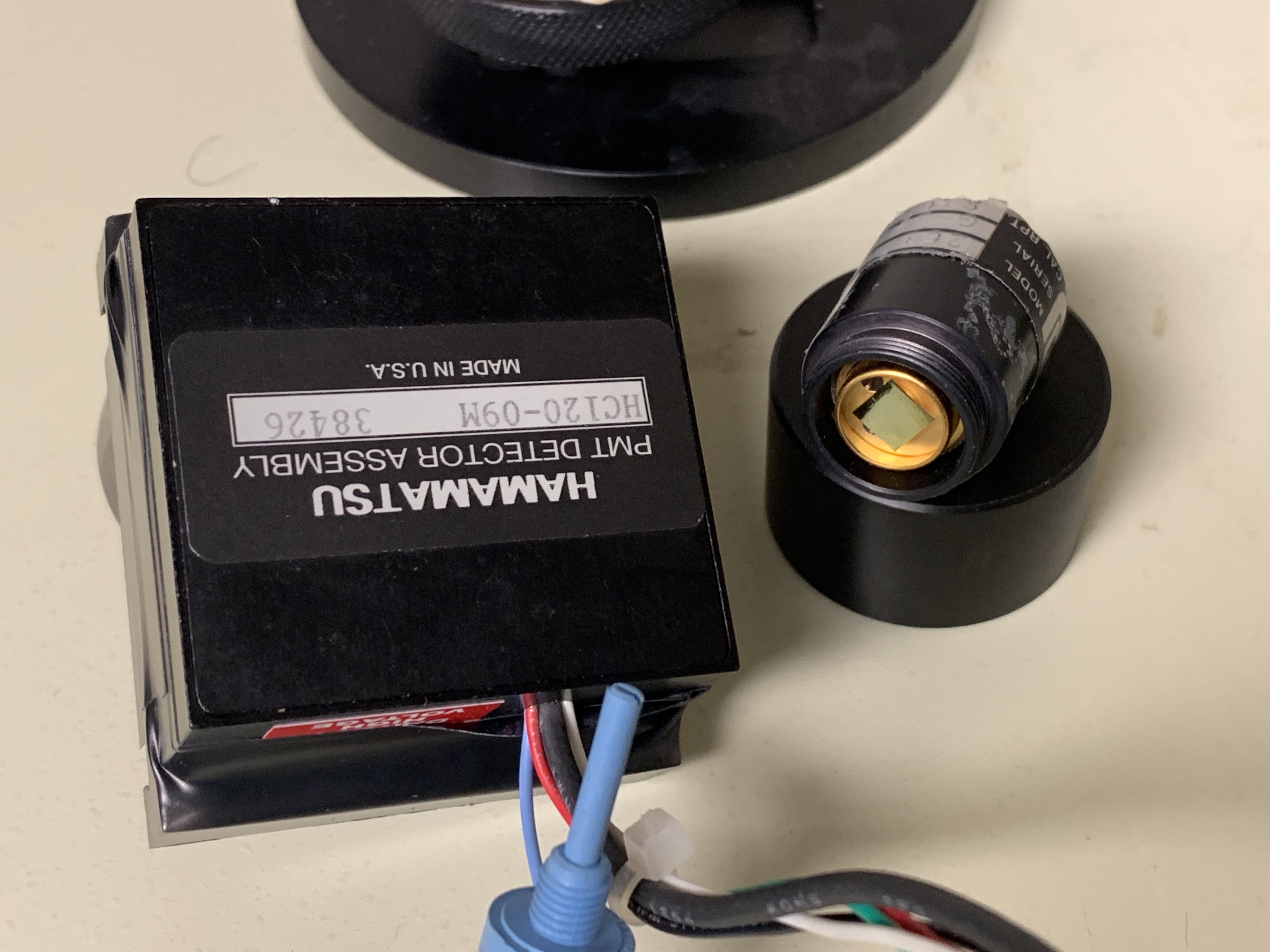
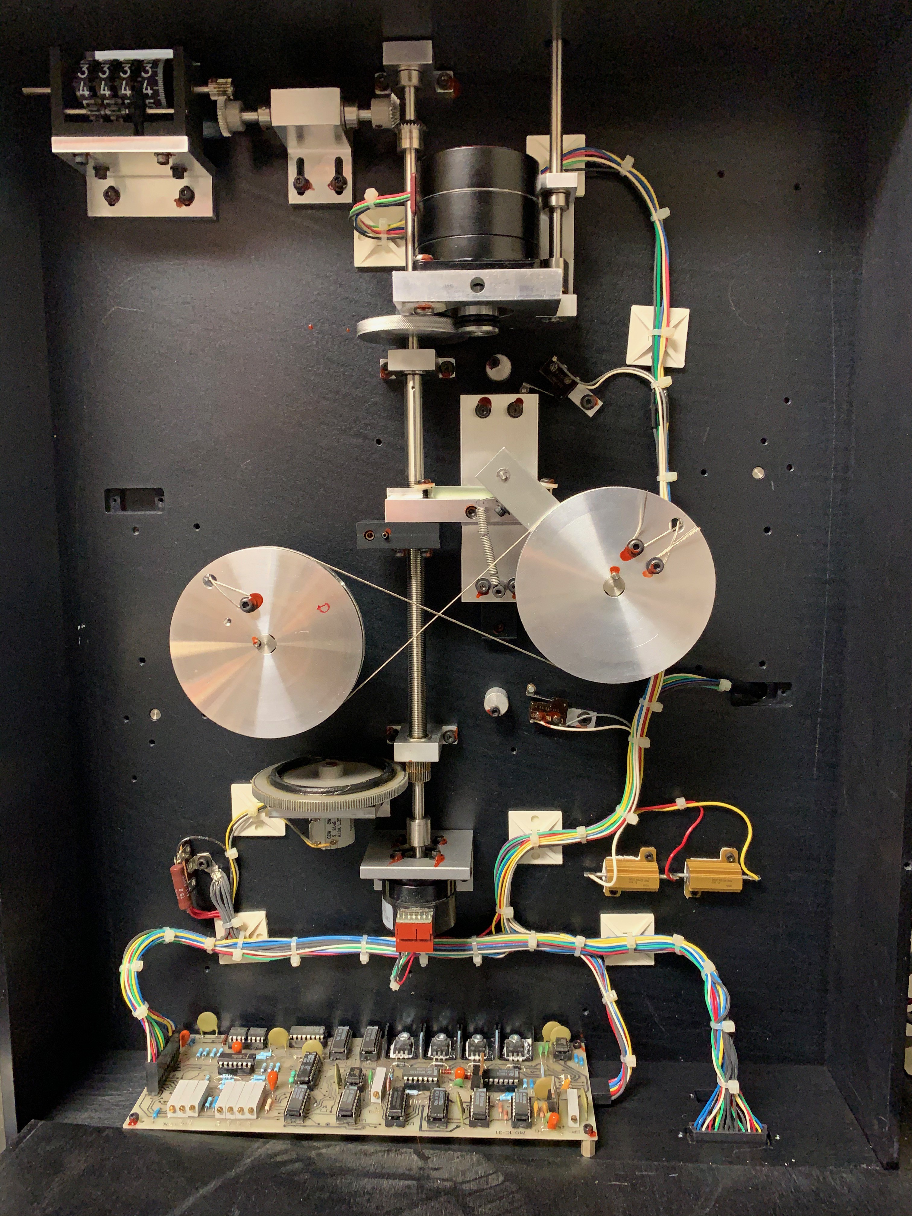
So about three years ago a friend and I picked up this old scanning monochromator that was used by SITe and Tektronix to test the quantum efficiency of their CCDs. Basically they treated the CCD as a giant photodiode and measured the current produced compared to the wavelength of light hitting it. This consisted of the following from Optronic Laboratories, now Gooch and Housego

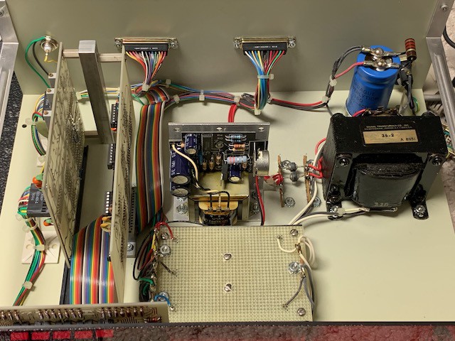
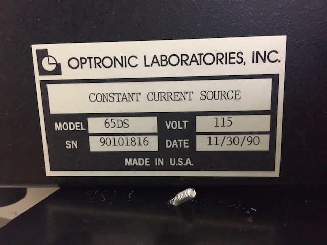
OL 65DS Constant Current Source - Lamp driver

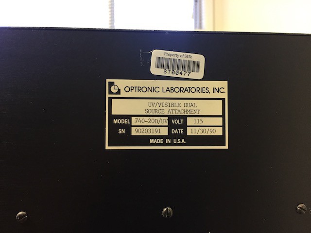
OL740-20D/UV  UV/Visible Dual Source attachment -Deuterium and Tungsten light source

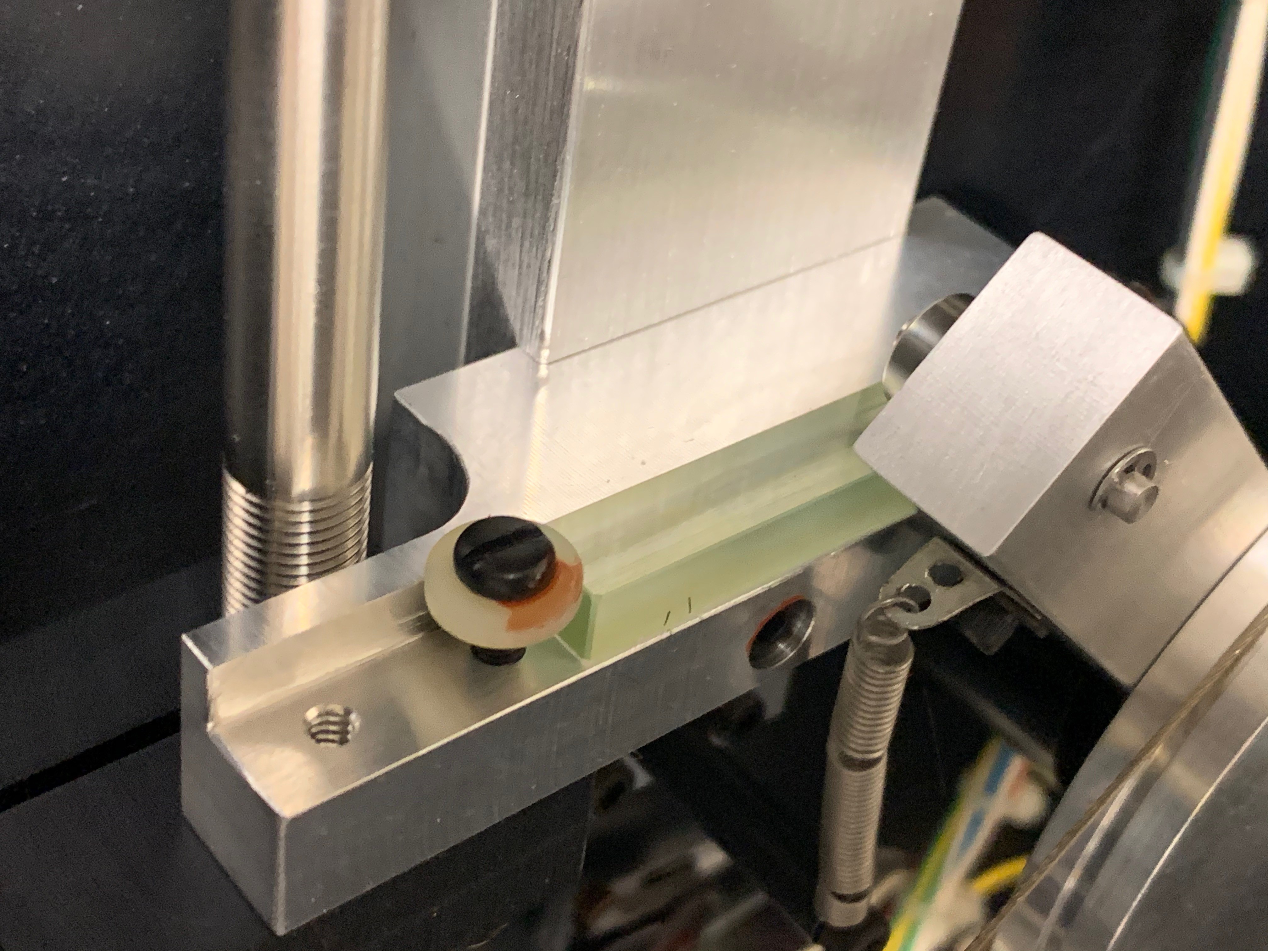
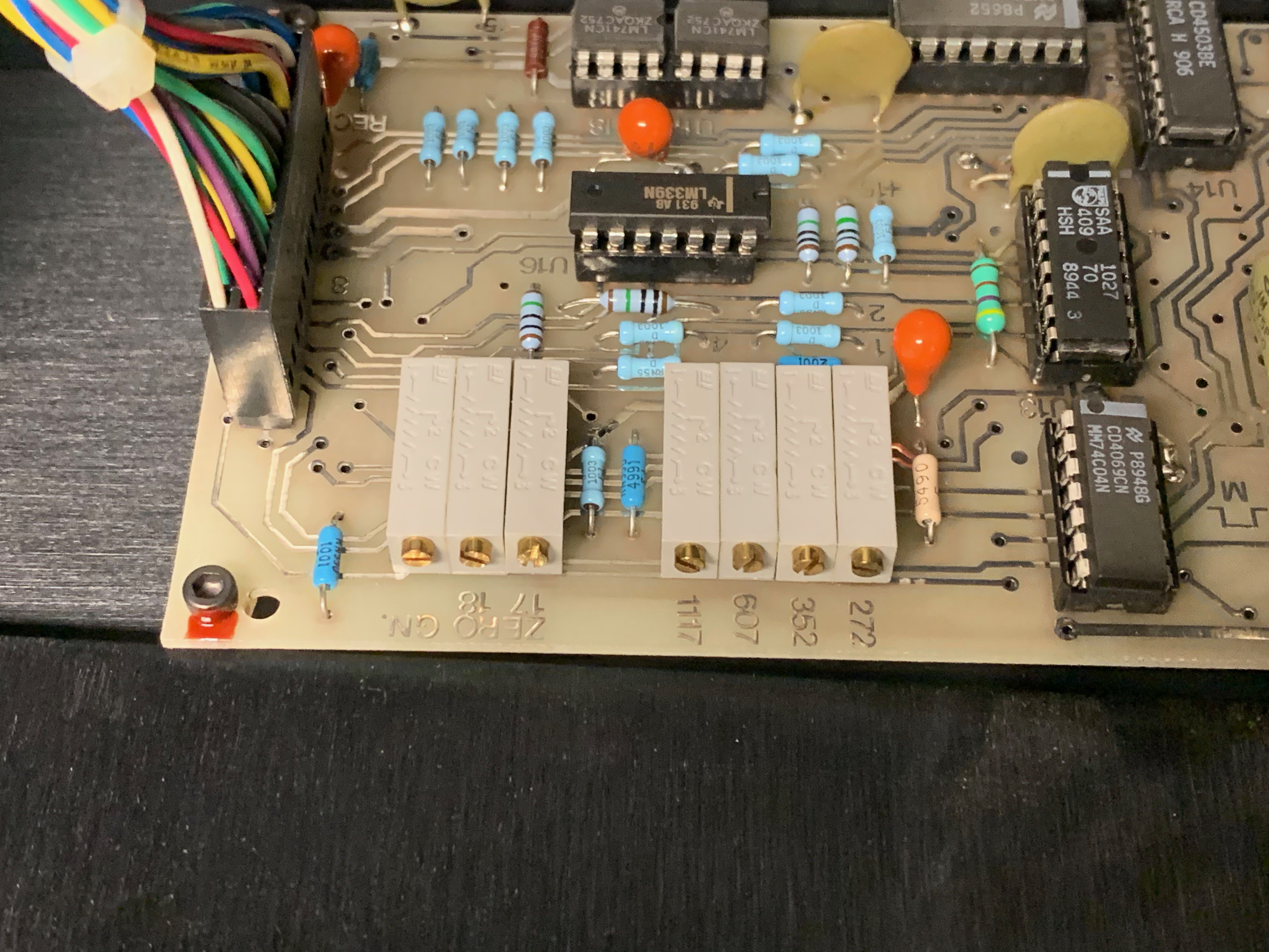
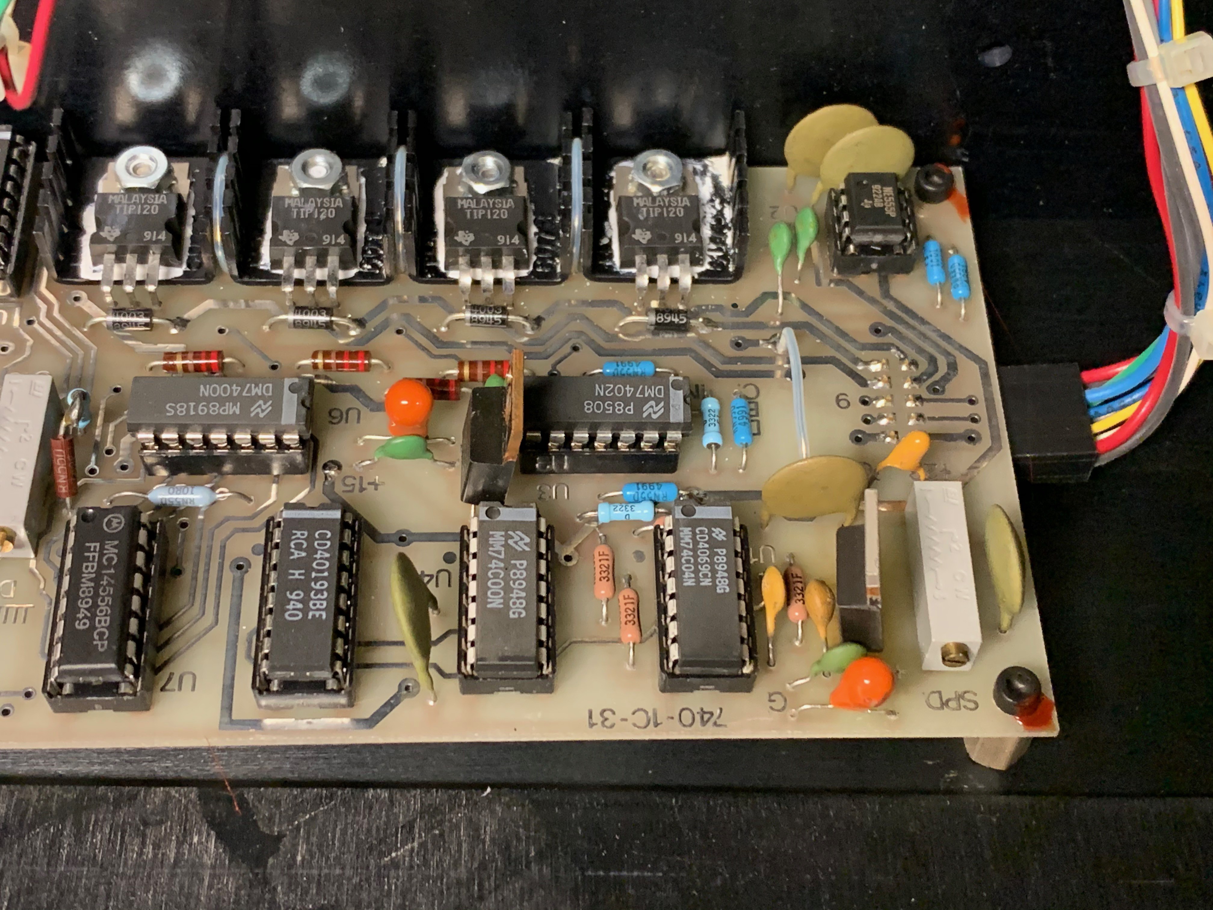
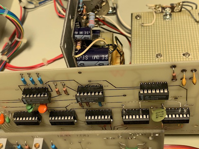
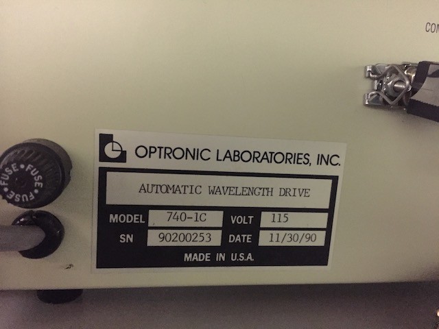
OL740-1C Automatic Wavelenth Drive - What controls the monochromator 

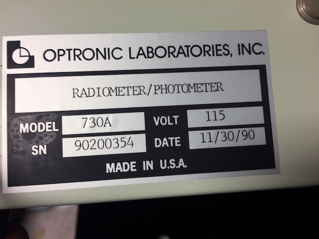
OL 730A Radiometer/Photometer - Basically a picoammeter.

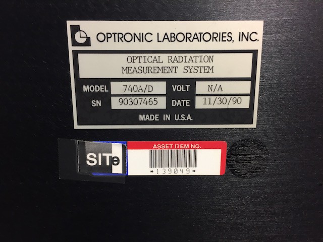
OL 740A/D Optical Radation Measurement System - The whole thing.

Uniblitz shutter controller

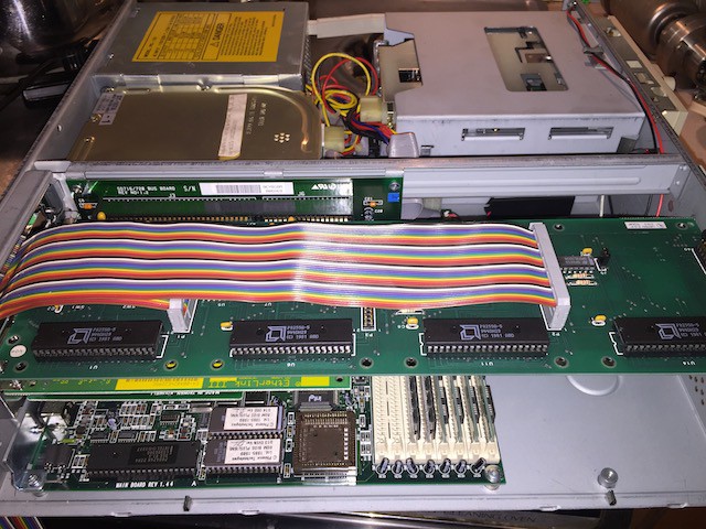
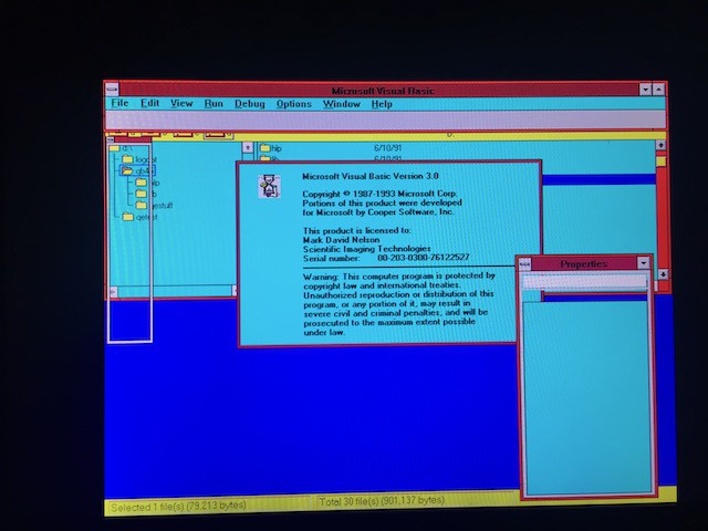
Leading Edge 386SX25 PC with DOS, BASIC,  and Windows 3.0

And a cart that it all went together on. 

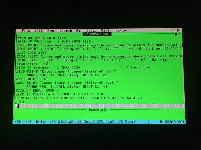
This had all been sitting since SITe shut down. The PC actually works and booted once I replaced the BIOS battery and set the hard drive cylinders and sectors. It has Win 3.0 but the program runs under DOS in BASIC. Good thing the computer worked because I would have had hell of a time getting this thing going again since manuals are completely non-existant. 

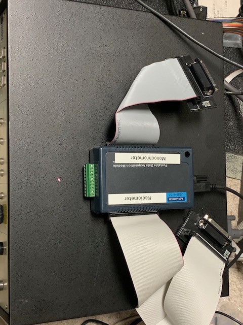
So the plan is to get this thing working with something more modern than DOS because it is a pain the butt to get files on/off and just to deal with the software in general. 

740DMA67.BAS

The BASIC program that ran the spectrometer.

bas - 77.36 kB - 11/22/2020 at 11:43

Download

  • Reflectance/Transmission Accessory

    Jerry Biehler01/07/2021 at 07:00 0 comments

    To make this thing useful for what I want to do I needed a reflectance and transmission accessory, this uses mirrors to bounce the beam from the monochromator through or against a sample at a set angle and then use a sensor to pick up what's left over. A friend actually has just what I needed, it was some sort of reflectance accessory that had been heavily modified for something with two spherical mirrors for handling the beam, one fixed and one on a circular translation that orbits the rotatable sample holder in the center. 

    I removed the small mirror which was on the orbiting bit and replaced that with a piece of black delrin I machined to hold different sensors. I removed the rest of the parts on the accessory that were no longer useful and machined a slot to hold the large mirror at a spot that would focus the beam on the sensor. 

    This all drops into a box I made out of some black scrap plastic that I had laying around. Had just enough to make the bottom and the sides, ill have to get some more to make a lid. The box slides over the output aperture of the monochromator and has feet that hold it up. The accessory drops in and lock in position with a couple pre-existing dowel pins in the bottom of the plate. 

    I also made a sample holder out of delrin that will allow me to mount mirrors with the first surface at the center of rotation so I can do reflectance measurements at various angles of incidence. You can see it below with one of the IR filters I test next. 

    For a first run I tested some IR filters I use for photography, I was curious if they actually different filters or the same glass put into different housings. 

    I tested three filters, one was an older C&G branded filter I got years ago when I modified one of my first cameras, I thought I had lost it until I stumbled upon it thinking it was one of my others I had bought for my modified Canon 5D Mark II. The other two are made by Zomei and I got these off ebay. The C&G and one of the zomei filters are supposed to be a 850nm long pass filter and the other Zomei is a 950nm long pass. 

    Looking at the resulting chart above I found several things. First, the UDT 261 germanium sensor acts really funny with the picoammeter are near zero light levels, the ammeter goes crazy. Once it gets the tiniest amount of light it settles down. This behavior has not been seen in any of the silicon or PMT sensors I have used. I will try to add a burden resistor across the diode to see if that helps quiet things down. 

    Second, the two 850nm filters are identical. They almost perfectly overlap. They seem to be about what they say they are.

    Third, I must of gotten a bit of bad data at about the 900nm mark, there is a bump across all three sample runs, if it was a sensor or beam path issue it should have been subtracted out. 

    Lastly, that 950nm filter SUCKS. What a mess. With that slow slope I am losing a lot of light which means I need to run a higher ISO which means more noise, so I will probably stick with the 850 until I find a better filter. 

  • Subtracting from the Baseline

    Jerry Biehler12/06/2020 at 12:58 0 comments

    I must have read 100 papers which talked about subtracting the baseline but didn't tell you how to do it. Finally I stumbled on https://publiclab.org/wiki/how-to-obtain-transmittance-absorbance-spectra where they give the equations to figure transmittance and absorbance. Its just division for transmission, sample/baseline. And it works too!

    This is the 900nm long pass filter I ended up using as the last order sorting filter. 

    I thought about putting this all in the program but I think I will do all the math and graphs in google sheets or excel. Its easier to mess with the data that way.

    So at this point the software and interface are pretty much done. Next I need to make a box to test filters. It will go between the output aperture of the spectrometer and the sensor with something internally to mount the optic I will test and the ability to set the angle of the optic. Probably also figure out a way to make it so I can put the sensor in the box and movable so I can measure reluctance on angle of incidence. 

  • Cleaning Up the Control Program and Another PMT

    Jerry Biehler12/05/2020 at 12:57 0 comments

    I found another PMT module I had with a different model number. I installed it hoping it would be the version with a photocathode that has sensitivity out into the red region. Yep! It did!

    Also figured it is time to clean up the software. Added a stop function so it stops the monochromator after you have started a scan or go-to sequence. I also added some stuff to handle files a little better, You can now run it without saving the data to a file. One you create a new save file it will automatically save to that file. You can also right click on the data table and copy that to a clipboard and save it to a spreadsheet.

    I also when through and tidied up the interface. Added and changed some indicators and just kind of got it a little better looking. 

  • PMT and Germanium Sensors, and calibration

    Jerry Biehler12/01/2020 at 09:50 0 comments

    It hit me the other night why I was seeing such terrible response at the NIR end of the spectrum, silicon sucks at detecting much past 1100nm. I have a UDT 261 Germanium sensor that is specifically designed for the 800 to 1750nm range. I machined an adapter to mount the .75"-32 threads to the monochromator of more black delrin. At least I think its delrin, it cuts a little funny.

    Much better response!

    The sensor I gave been using for the visible spectrum is a UDT UV100 silicon photo diode. It works pretty well for brighter conditions using the larger slits but when you start using the smallest slits you start getting into the noise floor. One possible solution to this was a Hamamatsu HC120 PMT module that I had pulled out of a Verity end point detector. I had no other information than this data sheet and my modules were a custom for Verity so Hamamatsu would not give me the details. I machined another adapter for that. It also needs a +/-15v power supply and an additional pot to control the internal high voltage power supply. 

    I plotted the curve of the PMT and it looks like it is probably a side window version of the HC120-01 module which really dies out around 650nm. This is with the PMT voltage set to 226v, the voltage was adjusted to not oversaturate the radiometer input. 

    Seeing it does work well for the UV end I warmed up the deuterium lamp and ran that though using both the UV and VIS gratings to see what it all looked like as well as ran the UV100 sensor.

    At the UV end both sensors match up well, you can see at about 450nm the PMT takes a nosedive where the UV100 keeps going though the end. So the PMT will be really good for any UV, especially since it is currently set at 226v with a maximum of 1100v, so it should be fine using the smaller slits. 

    One thing you can do with the deuterium lamp is used it to calibrate the spectrometer. There are two lines you can look at, Ha and Hb, the Ha line being the peak at 656.28 which you can see in each of the scans taken with the UV lamp above, the peak is not defined because I was using a 10nm step. To calibrate you just get close to 656nm and watch the output of the radiometer to peak and check the indicator on the monochromator and calculate the offset from what it reads and what it really is, in the case of my unit the visible offset was +1.5nm and the UV offset was +1.3.

    Still have not found out how to normalize the output.

    The two sensors I made adapters for.

  • Order Sorting Filters

    Jerry Biehler11/24/2020 at 11:14 0 comments

    The order sorting filters prevent second and third order reflections from the gratings from interfering with the output. They are long pass filters, one around the 350nn range as well as 600nm range, some have filters higher and lower, this one has one down in the deeper UV as well as a spot for one in the NIR area. And thats why I was getting such a sharp cut off at 1115nm, there was no filter installed, just a blank black aluminum disc. The wheel uses standard 1" filters, I had a bunch of different ones in the NIR range so I checked them out on the spectrometer. Unfortunately they were all notch filters like this one here:

    It is rated for 880nm and a 20nm pass which is pretty dead on. 

    Earlier this year I picked up a little Acton SpectraPro150 from the tektronics company store, it is a little unit maybe about 8"on a side and is controlled by an on-board serial or GPIB port. On a later visit I found the order sorting filter wheel that went with it and picked up that too. Someone added a 900nm long pass filter to that (and marked what they had added) at some point. That sounded like just what I needed so i popped it out and put it in the beam path to check it out before installing it.

    Yep, exactly what it said it was. So it is now installed in the filter.

    Now I need to figure out how to do baseline subtraction. Its harder than I thought it was going to be and have not have had any luck finding out what kind of math I need to handle that. 

  • Opening it up

    Jerry Biehler11/24/2020 at 10:59 0 comments

    After reading a research paper where they were looking at using one of these unit and the mention of bad drive belts in the wavelength drive I popped the monochromator off the table and pulled off the cover. Pretty neat design:

    The wavelength is selected bu moving a delrin nut aiming a ground thread rod, that moves a bracket that holds a glass plat which a cam follower runs against and rotates the gratings, the two gratings are coupled with tensioned steel cables for zero backlash. At the bottom of the threaded shaft is the encoder which sends the position signal back to the wavelength controller and next to that is a 10 turn pot on a gear. 

    That took me a bit to figure out, it's what controls the order sorting filter. I had known the filter was operated separately from the wavelength controller, I had figured there were just maybe some opto interrupters or something that controlled the position. Nope, they used a 10 turn pot which feeds into the board at the bottom. That board has a quad comparator and measure the voltage of the wiper and as it passes each set point set by the grey trimmers it selects the next filter position. There is a little stepper motor that belt drives the filter wheel which just keeps rotating until a magnet in the wheel travels over a reed switch for whichever position was selected. Simple!

    The drive is accomplished by the Vexta stepper at the top, it is driven by the board at the bottom by what looks like a very simple unipolar stepper design. The motor has two o-rings on an aluminum pulley with a cam mechanism that engages it against a knurled wheel when you want to drive it with the control. Good thing I did pop it open, there was not much left of the o-rings.

    So I replaced the rings and took some Krytox 240AC and greased the gears and popped it back together, it does run a little more smoothly now.

  • Putting it all back together

    Jerry Biehler11/23/2020 at 05:34 0 comments

    Now that it works I need to put it all back together. I took the adapter boards and covered the solder connections with tape so they dont short on anything and put a piece of 3M scotchlok on there if I want to mount them. The DB-25 connectors on the control boxes also used bail restraints instead of jack screws so I had to pop open the boxed to replace the bails with standoffs for the jackscrews. 

    Here is inside the radiometer, you can see the little reed relays for the range selection. nothing terribly complex. :

    The wavelength controller, one thing I notice is there is not power semiconductors for the motor, so I am guessing that is all in the monochromator unit itself.

    Finally here is the USB DIO unit and adapter boards.

  • Writing the program

    Jerry Biehler11/22/2020 at 23:26 0 comments

    I mentioned in the Vacuum System project that LabVIEW has quite a learning curve, since then I am working a job where I have used it a couple times to build test fixtures and even taken all of the official LabVIEW courses. And I still have issues wrapping my head around it. A lot of times it is throwing things at the screen and see if it works, lol.

    Anyway with the basic program in hand I read through it and just recreated the same program in labview, i managed to find someone that already had a library for LV that handled the 8 bit to BCD conversion I needed so that greatly simplified things. While I was waiting for the corrected boards to show up I went ahead and wrote sections of code to replicate the front panel buttons on the wavelength control and also made a "Go To" state machine loop that allowed me to type in a wavelength and it would go to it. It determines if the Go To wavelength is below or above the current wavelength and then determined how fast it should approach that point based on how far away it was. The spectrometer always approaches the set point from below, so say we set it to 400nm and we are at 500nm, the drive will drive it at high speed to 397nm, stop and then creep slowly to 400nm and stop. If the spectrometer is at 300nm it drives fast to 398nm and then creeps slowly to 400nm and stops. If it is at 397nm it just creeps slowly to the set point.

    Once the new adapter boards showed up I gave it a try and both the spectrometer control and the radiometer readout worked with only a bug each. The state machine did not fare so well, I goofed on some of the comparisons and had to fix that but it was not too bad.

    Next I tackled saving files. Oh boy this was more difficult that it should have been, I probably spent 6 hours trying to get it to save files all the while heading down a dead end path, it just kept dumping data into files even of the machine was not scanning. It all came down to using a value(signaling) tag to trigger the save but it did not operate like I thought. I spent hours thinking I had a signal noise issue and it was just my lack of understanding how it worked. I found out I just needed to have the save inside a state machine, so that means I need to do the next part, the actual scan control.

    For this part I wanted to set the beginning and end wavelengths as well as the interval at which it scans. Also open the shutter and close it at the end of the scan. This took a couple evenings of writing and debugging and tweeting to get it to work like I like, it reuses a lot of the code from the Go To program and then expands on it. 

    Works like this:

    Goes to the start wavelength as before

    stops

    opens the shutter,

    waits a programmable dwell period

    saves the radiometer value

    looks to see how far the next increment is to determine how fast it should move

    repeat stop, dwell, save, and increment until it hits the end point set.

    The UI is a mess and I am still tweaking things but it works pretty well now. 

    Here is a link to data from a scan, the little blip at 600 nm is from the order sorting filter kicking in.

    https://docs.google.com/spreadsheets/d/1MdD0yKilnuQckeJft5rbXBEczfmlWMYU_N0Zu94I_wA/edit?usp=sharing

  • Random Pics

    Jerry Biehler11/22/2020 at 22:54 0 comments

    Some Random Pics

  • Finally doing something with it.

    Jerry Biehler11/22/2020 at 12:22 0 comments

    It's a really nice unit, dual grating with gratings on each turret for UV and Visible spectrum. With the current setup it is good for about 200nm to 1115nm. The Du lamp handles 200-400nm and the tungsten covers the rest. It also has the 740-4P Off Axis Telescope.

    So the whole 386 and DOS/BASIC makes it a real pain to use, plus the program is pretty dedicated to doing the QE tests and I really dont want to learn basic to run it plus I would still have to deal with the ISA IO card it runs from,

    So i decided to make a new controller. For the hardware interface I ended up going with an Advantech USB-4751 48-Channel TTL Digital I/O USB Data Acquisition Module. It is pretty much the card inside of the old PC but in USB form. It uses two 50 PIN Opto-22 style ribbon connectors instead of the 40 pin headers on the ISA card. To transition to the DB-25 for the boxes I designed a small board that handles the transition from ribbon to DB-25. I did this in Altium since I use it for work. 

    Of course one cannot make a board without screwing it up. And boy did I! Every connection was wrong. Somehow I managed to get the order of pins wrong on the 50 pin header and then the footprint I used in Altium for the DB-25 was totally wrong. So I literally did not get one pin right. So I fix that and send of another order to JLCPCB and a week later I get good boards. 

    So now that the hardware is "Done" I tackle the hardware. I cant program worth a damn so I use LabVIEW which I also use for work. The advantech DIO device has good LabVIEW drivers that make it pretty easy to build an interface. Well, compared to the first unit I picked up from SeaLevel, it was an older unit and didn't have any really labview drivers and I really didn't feel like figuring it out so I picked up the Advantech. $111 shipped, not bad!

View all 11 project logs

Enjoy this project?

Share

Discussions

Similar Projects

Does this project spark your interest?

Become a member to follow this project and never miss any updates